41
Connection
A
to con-
trol unit
Circulation pump
C
Heating circuit without mixer A1/HC1
■
Without heating water buffer cylinder 211.2 Secondary pump
■
With heating water buffer cylinder 212.2 Heating circuit pump A1/HC1
Heating circuit with mixer M2/HC2 225.1 Heating circuit pump M2/HC2
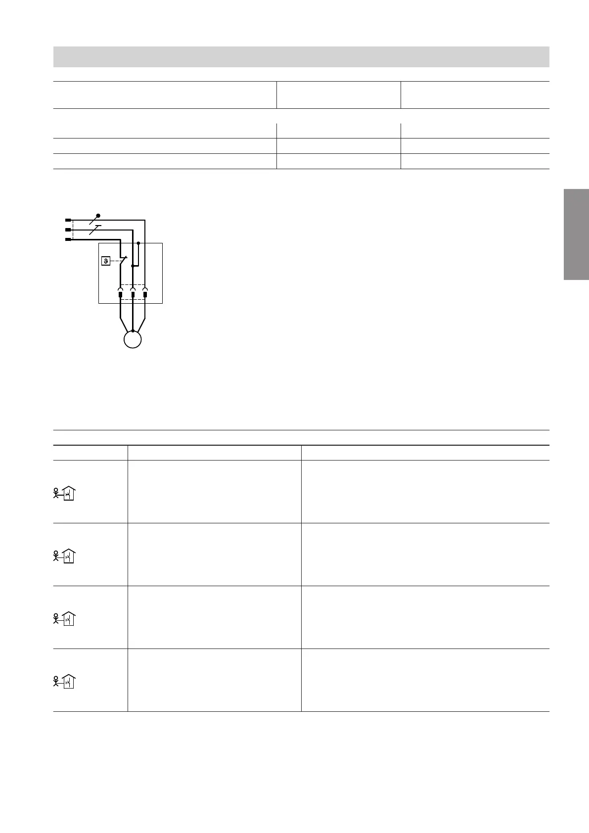
Connecting the temperature limiter, part no. 7151728,
7151729
B
to the mixer extension kit
Fig. 36
A
Connect plug
sÖ
to the extension kit.
B
Temperature limiter
C
Heating circuit pump M3/HC3
Plug
sYF
Terminals Function Explanation
214.1
M2
External hook-up, heating/cooling cir-
cuits:
Central heating demand, heating cir-
cuit M2/HC2
230 V~ digital input:
■
230 V~: Central heating demand for heating circuit
M2/HC2 active
■
0 V: No demand
■
Breaking capacity 230 V~, 0.15 A
214.2
M2
External hook-up, heating/cooling cir-
cuits:
Central cooling demand, heating cir-
cuit M2/HC2
230 V~ digital input:
■
230 V~: Room cooling demand for heating circuit
M2/HC2 active
■
0 V: No demand
■
Breaking capacity 230 V~, 0.15 A
214.3
M3
External hook-up, heating/cooling cir-
cuits:
Central heating demand, heating cir-
cuit M3/HC3
230 V~ digital input:
■
230 V~: Room heating demand for heating circuit
M3/HC3 active
■
0 V: No demand
■
Breaking capacity 230 V~, 0.15 A
214.4
M3
External hook-up, heating/cooling cir-
cuits:
Central cooling demand, heating cir-
cuit M3/HC3
230 V~ digital input:
■
230 V~: Room cooling demand for heating circuit
M3/HC3 active
■
0 V: No demand
■
Breaking capacity 230 V~, 0.15 A
Installation sequence
Electrical connection (cont.)
6199585
Installation
 Loading...