24
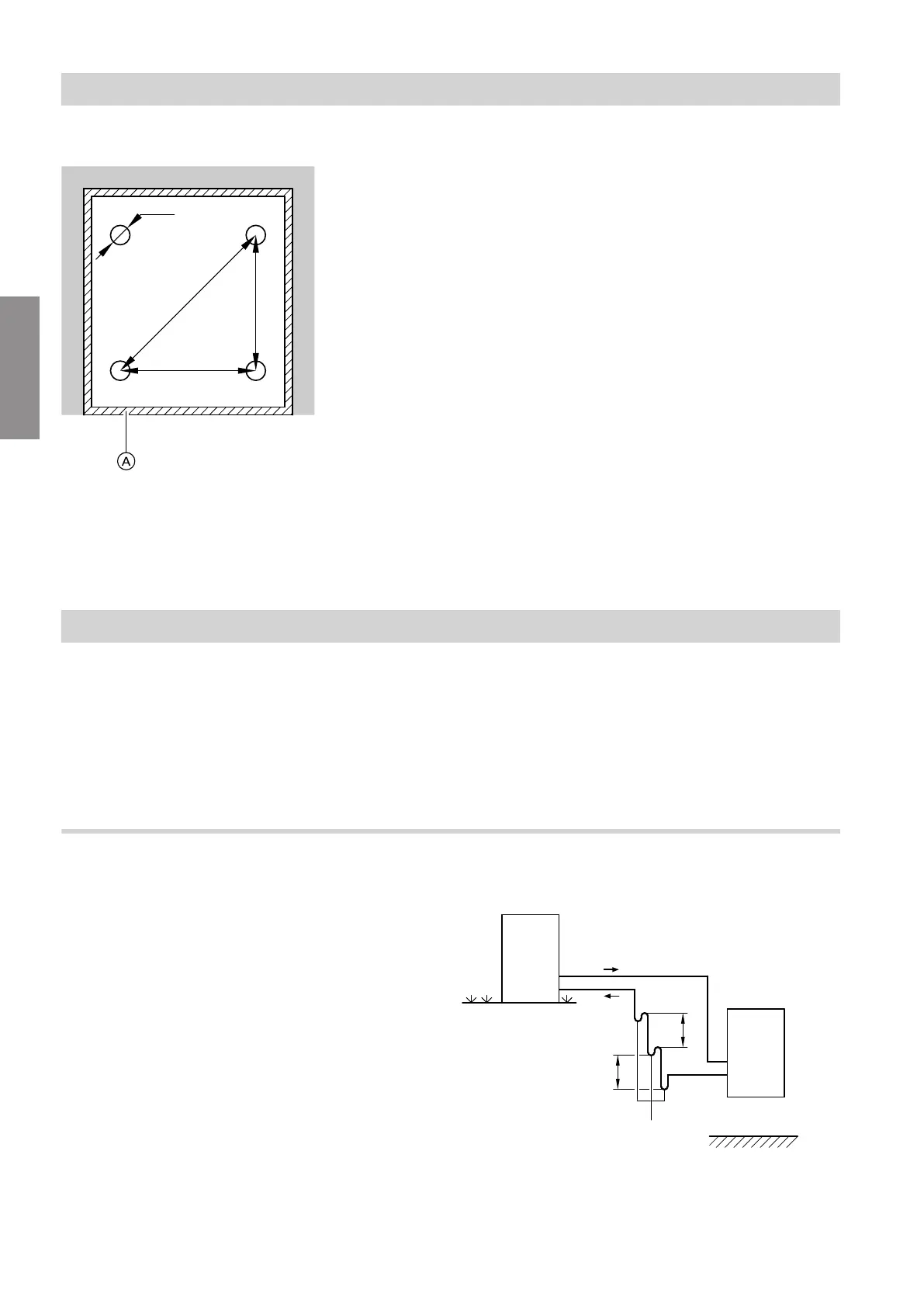
Pressure points
Fig. 16
A
Partition joint with edge insulation strip as part of
the floor construction
a 439 mm
b 506 mm
c 670 mm
d 64 mm
Note
■
Observe the permissible floor load.
■
Level the appliance horizontally.
■
If the adjustable feet are used to compensate for an
uneven floor (max. 10 mm), distribute the pressure
load on the individual feet evenly.
Total weight with filled DHW cylinder
■
Vitocal 111-S with 1 fan:
384 kg
■
Vitocal 111-S with 2 fans:
387 kg
Each pressure point (each with an area of 3217 mm
2
)
is subject to a load of up to 96 kg.
Connecting the refrigerant lines
■
The outdoor unit is precharged with refrigerant.
■
The diaphragm grommets for sealing the opening for
the refrigerant lines are included in the standard
delivery of the indoor unit.
■
Refrigerant lines with flammable refrigerant (R32)
must be laid between the indoor and outdoor units
without interruption (EN 60335).
Oil lift bends
Oil lift bends guarantee that the refrigerant oil is relia-
bly conveyed back to the compressor.
!
Please note
Errors in the design and installation of oil lift
bends can result in appliance damage.
■
The outdoor unit is installed more than 5 m
above the indoor unit:
Install oil lift bends in the vertical hot gas line.
■
Indoor unit is installed above the outdoor unit:
Do not install oil lift bends.
Outdoor unit higher than indoor unit
Fig. 17 With oil lift bends
A
Outdoor unit
B
Hot gas line
Installation sequence
Installing the indoor unit (cont.)
6199592
Installation


 To Next Page