25
C
Liquid line
D
Indoor unit
E
Oil lift bends
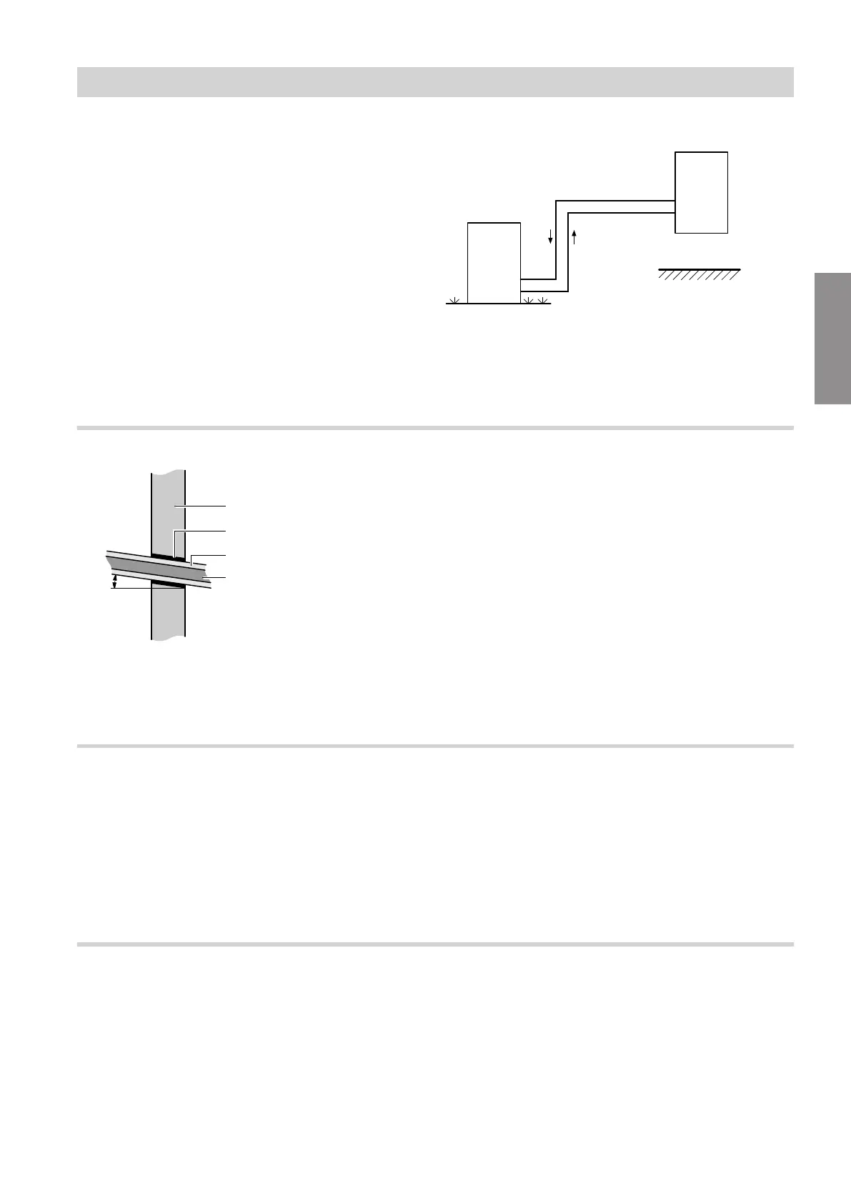
Indoor unit higher than outdoor unit
Fig. 18 Without oil lift bends
A
Outdoor unit
B
Hot gas line
C
Liquid line
D
Indoor unit
Wall outlet
Fig. 19
A
Outside the building
B
Wall
C
PVC or PE pipes, etc.
D
Closed cell diffusion-proof thermal insulation
E
Refrigerant lines
F
Inside the building
The indoor and outdoor units are connected to the
refrigerant lines and the connecting cable. Wall outlets
are required for this purpose. With these wall outlets,
be aware of load bearing sections, lintels, damp proof-
ing elements (e.g. vapour barriers), etc.
Note
In order to prevent structure-borne noise transmission,
the refrigerant lines must not come into contact with
PVC or PE pipes.
Line lengths
■
Max. height differential, indoor unit – outdoor
unit:
15 m
■
Min. line length:
5 m
■
Max. line length:
Types B04/06/08: 25 m
Types A12/A14/A16: 30 m
Note
No additional charging is required for line lengths up to
10 m: See page 62.
Sound insulation and vibration isolation
Information on installing the cables and lines
Wall outlet:
■
No wall outlet where load bearing sections, lintels,
damp proofing elements (e.g. vapour barriers), etc.
are located.
■
No structure-borne noise transmission, i.e. avoid
contact between metal (refrigerant line) and the
building structure.
Routing the cables and lines:
■
Route cables free of strain and separated from the
refrigerant lines.
■
Route the hot gas line with pipe bends. This reduces
the transmission of vibrations to the pipe wall.
■
Use a tighter pipe bend for vibration compensation
on a shorter hot gas line than on a longer hot gas
line.
■
Insulate all refrigerant lines.
Installation sequence
Connecting the refrigerant lines (cont.)
6199592
Installation


 To Next Page