60
Note
■
Moving the control unit panel into the service posi-
tion:
See page 80.
■
Opening the programming unit:
See page 79.
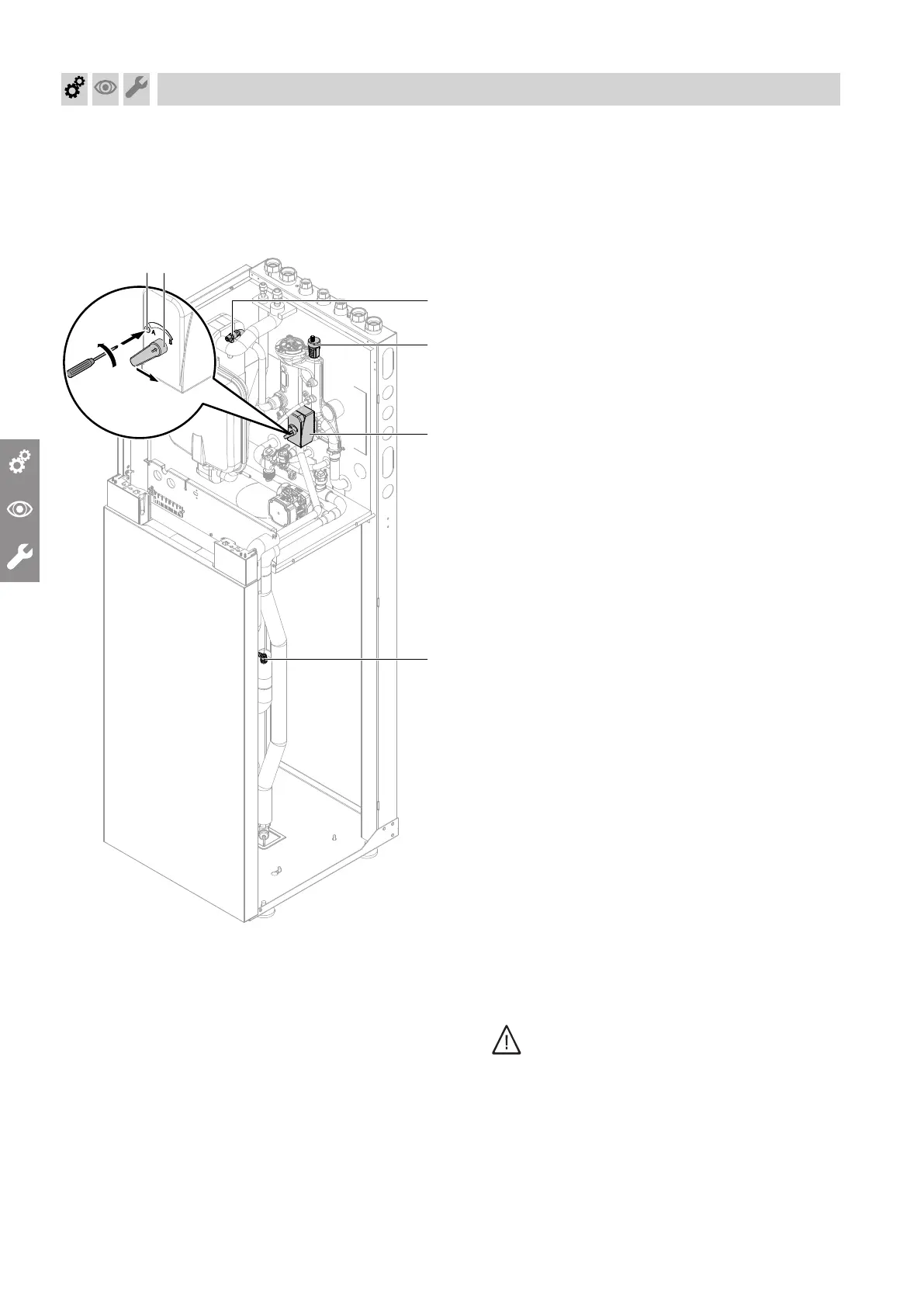
Fig. 51
01. Open any non-return valves installed on site.
02. Check the pre-charge pressure of the expansion
vessel. Adjust the pre-charge pressure to match
the system conditions if necessary.
03. Fill (flush) and vent the secondary circuit via an
on-site connection.
!
Please note
To prevent appliance damage, check the
secondary circuit flow and return connec-
tions on the appliance for leaks.
In the case of leaks, switch off the appliance
immediately, drain the water and check the
seating of the seal rings. Always replace
displaced seal washers.
04. Check the system pressure at the pressure gauge.
Top up with water if required.
■
Minimum system pressure:
0.8 bar (80 kPa)
■
Permissible operating pressure:
3.0 bar (0.3 MPa)
05. Move the control unit panel into the service posi-
tion.
06. Open the programming unit.
07.
Slightly open quick-action air vent valve
B
; it
remains open.
Connect the on-site hose to secondary circuit air
vent valve
C
.
!
Please note
Escaping liquids can lead to electrical
defects.
Protect electrical components from escap-
ing liquids.
08.
Open secondary circuit air vent valve
C
.
Danger
Escaping hot water and hot steam can
cause serious injury and damage the heat-
ing system.
Only open drain and fill valves when the
heating system is cold.
09.
Move 3-way diverter valve
A
to its centre posi-
tion: Press
D
and turn anti-clockwise to lock to
the "MAN" position. Move lever
E
to a vertical
position.
Commissioning, inspection, maintenance
Filling and venting on the secondary side (cont.)
5831412