85
D
Electronic expansion valve
E
4-way diverter valve
F
Secondary circuit flow temperature sensor
upstream of instantaneous heating water heater
(T1)
G
Low pressure sensor
H
Secondary circuit air vent valve
K
Evaporator suction gas temperature sensor (T7)
L
Reversible suction gas temperature sensor (T3)
M
Condenser
N
Schrader valve, low pressure side
O
Hot gas temperature sensor (T6)
P
Compressor suction gas temperature sensor (T4)
R
Schrader valve, high pressure side
S
Compressor
T
Refrigerant receiver
U
Safety high pressure switch
V
High pressure sensor
W
Schrader valve, high pressure side
X
Refrigerant circuit controller temperature sensor
(T2)
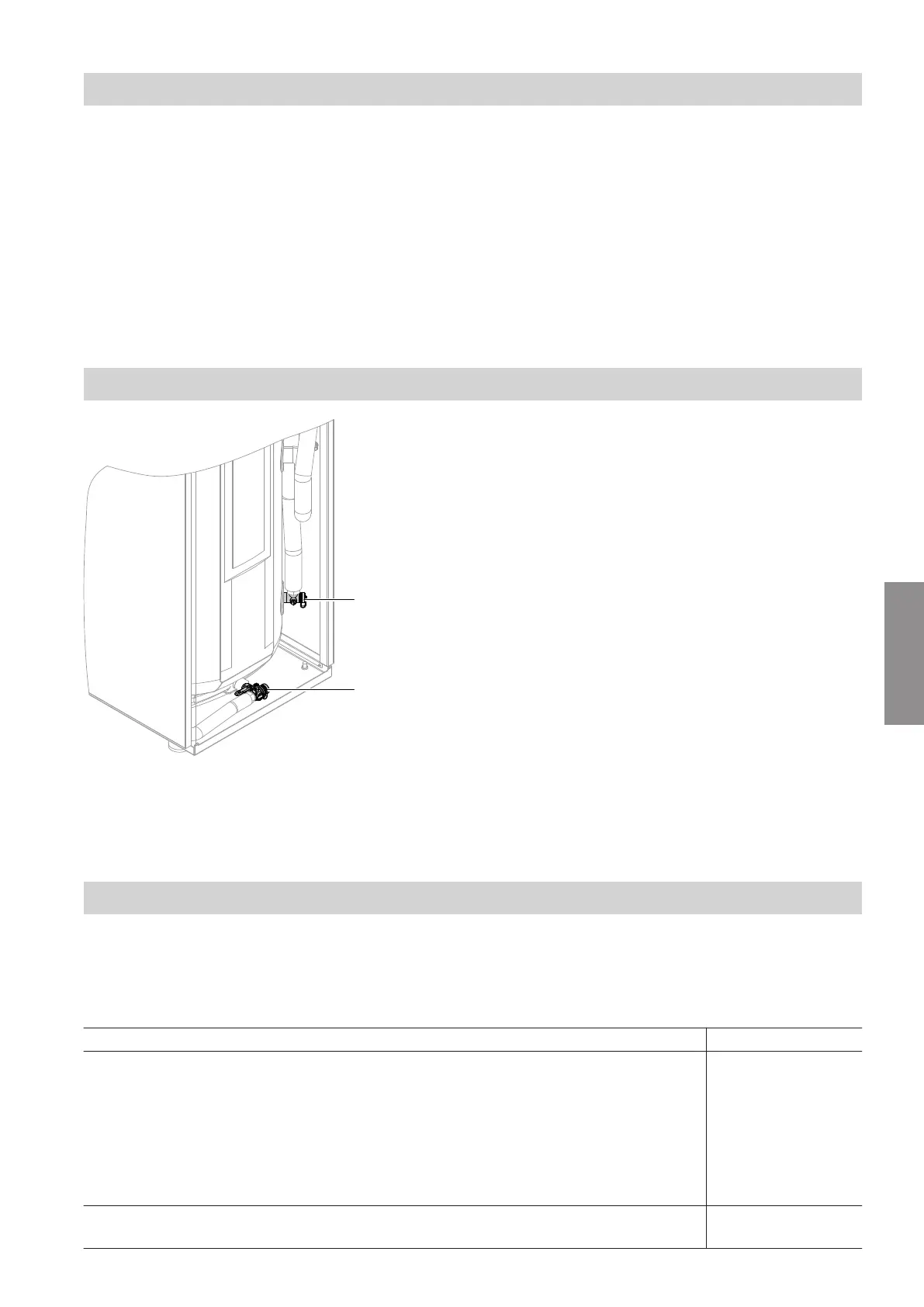
Draining the heat pump on the secondary side
Fig. 68
A
Drain and fill valve, secondary side
B
Drain and fill valve, DHW side
1. Close the on-site boiler drain and fill valve.
2. Draining the heating water side
Connect the hose to the drain and fill valve of the
secondary circuit.
Open the secondary circuit drain and fill valve.
3. Draining the DHW side
See chapter "Draining the appliance on the DHW
side", page 64.
Checking the temperature sensors
Connection to the indoor unit
Temperature sensors are connected to the controller
and sensor PCB: See page 41.
Temperature sensor Test element
■
Outside temperature sensor (F0)
■
Buffer temperature sensor (F4)
■
Cylinder temperature sensor, top (F6 or X25.5/X25.6, see service instructions for
"Vitotronic 200, type WO1C")
■
Flow temperature sensor, heating circuit with mixer M2/HC2 (F12)
■
Cooling circuit flow temperature sensor (direct heating circuit A1/HC1 or separate cool-
ing circuit SKK) (F14)
■
Room temperature sensors
NTC 10 kΩ
■
Secondary circuit flow temperature sensor (F8)
■
Secondary circuit return temperature sensor (F9)
Pt500A
(PTC)
Maintenance
Overview of internal components: Outdoor unit (cont.)
5831412
Maintenance