6
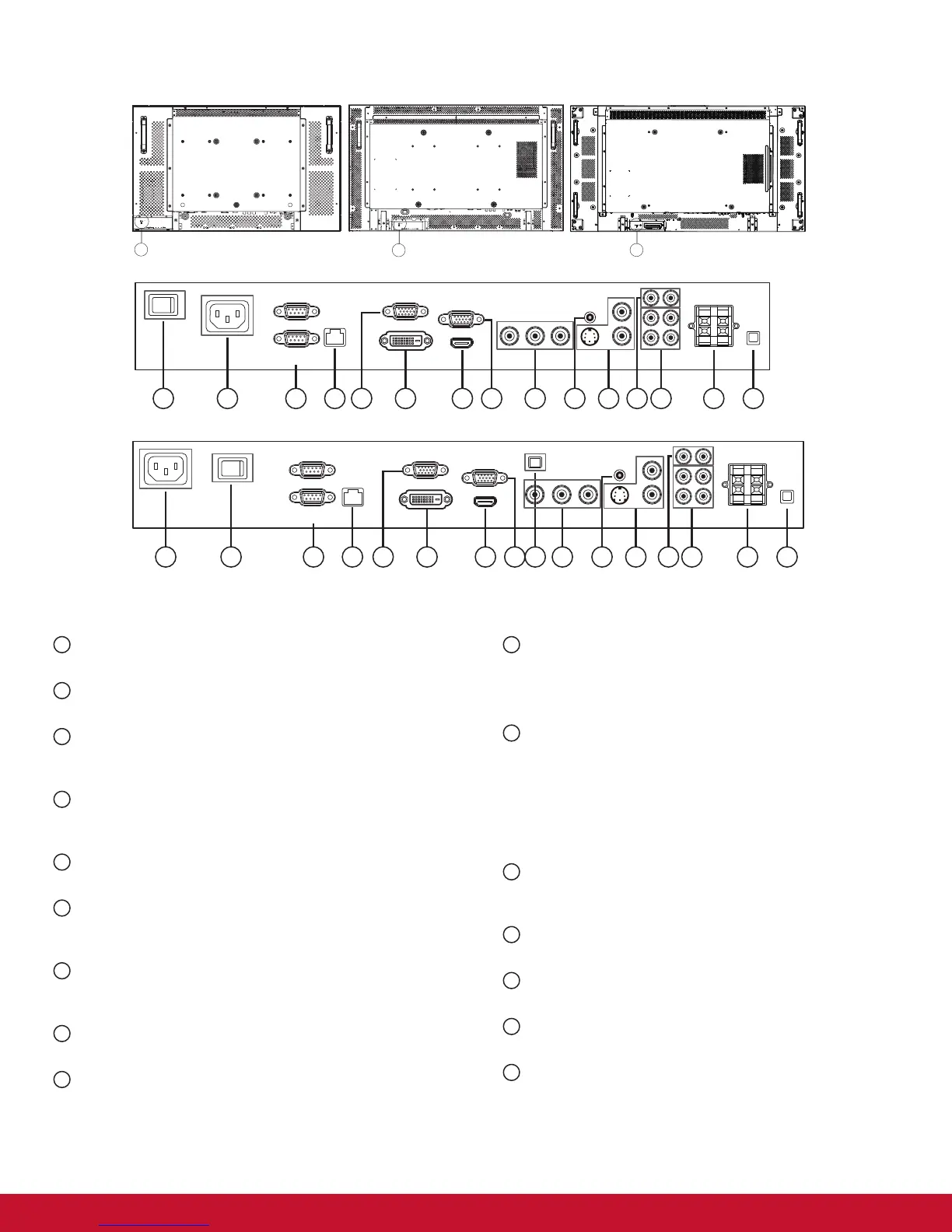
2.2. Input/Output Terminals
(OUT)
CDP3235
CDP4235/CDP4635 series
CDP3235
CDP4235/CDP4635/CDX5550-L series
16
1 2 3 4 6 7 9 1110 13 141085
15
15
(IN)
(OUT)
Pr Pb Y
(IN)
(IN)
(OUT)
1
12
(OUT)
12 3 4 6 7 9 1110 13 141085
(IN)
(OUT)
3
2
Pr Pb Y
(IN)
(IN)
(OUT)
1
12
3
2
15
CDX5550-L
1
MAIN POWER SWITCH
Press to switch the main power on/off.
2
AC IN
Connect the supplied power cord to the wall outlet.
3
RS232C (OUT/IN)
RS232C network input/output connection for the use of loop-
through function.
4
RJ-45
LAN control function for the use of remote control signal
from control center.
5
VGA OUT (D-Sub)
Output the VGA signal from the VGA IN (D-Sub).
6
DVI-D IN
Connect the DVI-D output of a PC, or the HDMI output of an
AV device by using a DVI-HDMI cable.
7
HDMI IN
Connect the HDMI output of an AV device, or the DVI-D
output of a PC by using a DVI-HDMI cable.
8
VGA IN (D-Sub)
Connect the computer VGA output.
9
COMPONENT IN (BNC)
Connect the component YPbPr output from external AV
device.
10
AUDIO IN 1, 2, 3
Connect audio input from external AV device.
• AUDIO IN 1: 3.5mm stereo phone jack
• AUDIO IN 2, 3: RCA phone jack
11
VIDEO IN/OUT
• S-VIDEO IN (Mini DIN 4 pin): Connect the S-VIDEO (Y/
C separate signal) input.
• VIDEO IN (BNC): Connect the composite video signal
input.
• VIDEO OUT (BNC): Connect the composite video signal
output from VIDEO IN (BNC).
12
AUDIO OUT R/L (RCA)
Connect the audio signal output from AUDIO IN 1, 2, or 3
jack to an external AV device.
13
SPEAKERS OUT R/L
Connect the audio output to external speakers.
14
SPEAKER SWITCH
Press to switch the internal speaker on/off.
15
KENSINGTON LOCK
For security and theft prevention.
16
USB-B
Touch connector to PC.