B"
""
"INSTRUMENT ALIGNMENT"
""
"
1. Defection Presets"
Control pots VR201&VR4403&VR4401&VR4402 are set at middle point. Screen'Focus VR set to min"
2. Power Supply Alignment"
2.1 Input VESA$1280*1024 @85Hz%signal cross-hatch pattern & beam current set at 0µA"
2.2 Adjust VR201 until TP201 = 180V(0.2V at TP201"
2.3 Input VGA(480) signal cross-hatch pattern&beam current set at 0uA
2.4 Adjust VR4401must be high voltage 27KV +/- 0.1KV .
2.5 Adjust Screen VR to let G2 580 +/- 10V
3. Size & Geometry Adjustment"
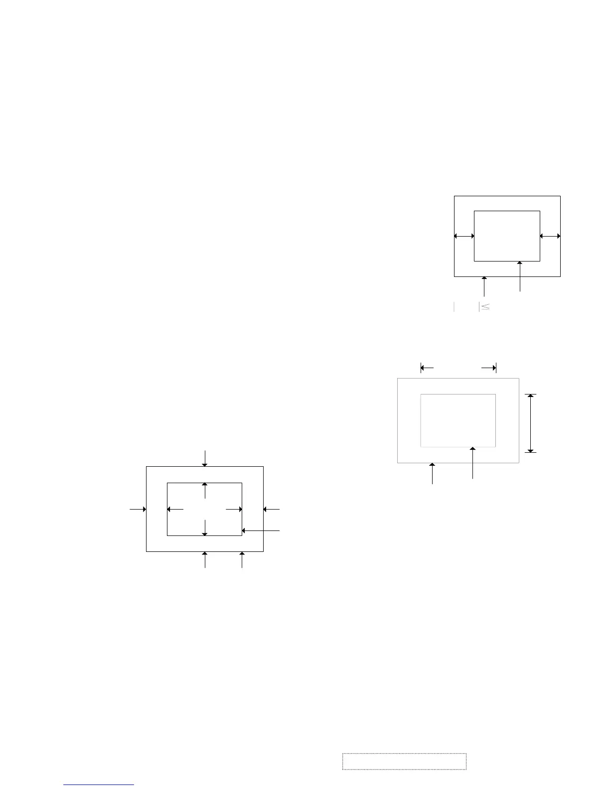
3.1 Raster Centering"
3.1.1 Input cross hatch pattern at 93K 1600*1200 mode"
3.1.2 Adjust contrast to 10FL'adjust screen just raster visible"
3.1.3 Adjust VR404 to center raster on screen such that the horizontal
distance from the midpoint of the left display edge to the
left bezel edge is within 2mm of the distance from
the midpoint of the right display edge to the right bezel edge"
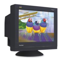
3.2 Picture Size"
Input mode 1~15 signal adjust V-size'H-size to achieve"
H-SIZE)390mm (2mm
V-SIZE)290mm (2mm
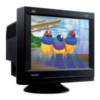
3.3 Picture Centering"
Input mode 1~15 adjust V-position'
H-position such that the picture is centered with the screen"
Beze
Picture
D
AB
C
A - B 2mm**+
C - D 2mm**+
AB
Beze
Raste
A-B 2mm
Bezel
Picture
357mm
268mm
390m
290m
ViewSonic Corporation
42
Confidential – Do Not Copy
G220f-1_G220fB-1