Do you have a question about the Viking pump 124A Series and is the answer not in the manual?
How pump rotation determines suction and discharge ports.
Guidelines for pressure relief valves on Viking pumps.
External lubrication requirements for Viking pumps.
Instructions for initial packing adjustment and replacement.
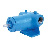
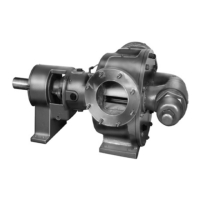
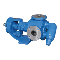
This document is a Technical Service Manual for Viking Pump's Universal Seal Heavy Duty Pumps, covering various series and sizes (LS, Q, QS & M). It provides comprehensive instructions for the installation, operation, and maintenance of these pumps, emphasizing safety precautions throughout.
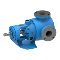
Viking Universal Seal Heavy Duty Pumps are positive displacement pumps designed for a wide range of industrial applications. They are capable of handling various liquids and are built for long, trouble-free service. The pumps operate equally well in clockwise or counterclockwise rotation, with shaft rotation determining which port is the suction and which is the discharge. The idler pin, an offset component in the pump head, must be positioned correctly to ensure proper liquid flow.
A key feature of these pumps is their universal seal design, which allows for different types of mechanical seals or packing to be used depending on the application requirements. The manual specifically addresses cartridge, elastomeric bellows, and PTFE wedge mechanical seals, as well as packed pump configurations.
For applications involving high-viscosity liquids or those requiring temperature control, some models are equipped with heat cartridges. These cartridges, typically installed in the head and bracket, are designed to melt or maintain the temperature of the liquid being pumped, preventing damage and ensuring proper operation. A closed-loop temperature controller is recommended for use with heat cartridges to minimize temperature overshoots and prolong cartridge life.
Pressure relief valves are an integral safety component for positive displacement pumps like these. They provide pressure protection by allowing liquid to bypass when discharge pressure exceeds a set limit. The manual details the disassembly, assembly, and adjustment of these valves, stressing that they cannot be used to control pump flow or regulate discharge pressure.
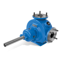
The pumps are designed for versatility, accommodating different drive styles (V-Belt, Direct Connected, Viking Speed Reducer, Commercial Speed Reducer) as indicated by a letter suffix in the unit model number. This adaptability allows for integration into various system configurations.
Proper installation is crucial for the pump's performance and longevity. The manual provides detailed steps for assembling the pump components, including the bearing housing, rotor, shaft, and idler assembly. Special attention is given to the installation of mechanical seals, with specific instructions for each type to prevent damage and ensure effective sealing. For packed pumps, instructions are provided for installing and adjusting packing to control leakage.
Thrust bearing adjustment is a critical step in setting the pump's end clearance, which affects its operational efficiency and lifespan. The manual outlines a precise procedure for adjusting the thrust bearing assembly to achieve the standard end clearance, with provisions for additional clearance for high-viscosity liquids.
For models equipped with heat cartridges, the manual provides detailed installation instructions, including the importance of proper grounding, anti-seize compound application, and insulation to minimize heat loss. It also specifies the electrical requirements for the heat cartridges and emphasizes the need for a licensed electrician for wiring.
The manual highlights several maintenance practices to ensure the pump's long and trouble-free service life. Regular lubrication of external fittings with multi-purpose grease is recommended every 500 hours of operation. For packed pumps, initial packing adjustment is necessary, followed by periodic inspection for replacement.
Cleaning the pump regularly is advised to facilitate inspection, adjustment, and repair work. For pumps that will be stored for six months or more, draining and applying a light coat of oil to internal parts, along with periodic shaft rotation, are recommended to prevent corrosion and ensure readiness for use.
The manual provides comprehensive disassembly and assembly instructions, allowing for component replacement and repair. It emphasizes marking parts before disassembly to ensure proper reassembly and outlines steps for removing the head, idler, rotor, shaft, and bearing housing. Specific instructions are given for handling mechanical seals and packing during disassembly and reassembly.
For carbon graphite bushings, which are brittle and require careful handling, the manual provides detailed installation instructions, including heating the bracket or idler and using a press to prevent cracking.
Safety is a paramount concern in all maintenance procedures. The manual repeatedly warns against opening liquid chambers without first venting pressure and locking out the drive system. It also stresses the importance of understanding the liquid being handled and following appropriate safety precautions, including consulting Material Safety Data Sheets (MSDS). The use of appropriate lifting devices and personal protective equipment is also emphasized.
The document also includes a warranty statement, outlining the terms and conditions of Viking Pump's warranty, which covers defects in material and workmanship under normal use and service conditions.
| Pump Series | 124A Series |
|---|---|
| Port Type | NPT or BSPP |
| Materials | Cast Iron, Stainless Steel |
| Seal Options | Mechanical Seal, Packing |
| Drive Type | Belt Drive |