EasyManua.ls Logo

Viking pump Q34 - User Manual

Default Icon
9 pages
Print Icon
To Next Page IconTo Next Page
Loading...
VIKING PUMP, INC. A Unit of IDEX Corporation Cedar Falls, IA 50613 USA
SECTION TSM 430
PAGE 1 OF 9
ISSUE D
TECHNICAL SERVICE MANUAL
CONTENTS
INTRODUCTION
The illustrations used in this manual are for identification
purposes only and should not be used for ordering parts.
Secure a parts list from the factory or a Viking representative.
Always give complete name of part, part number and material
with the model and serial number of the pump when ordering
repair parts.
Introduction . . . . . . . . . . . . . . . . . . . . . . . 1
Special Information . . . . . . . . . . . . . . . . . . . 1
Safety Information. . . . . . . . . . . . . . . . . . . . 2
Maintenance . . . . . . . . . . . . . . . . . . . . . . 3
Disassembly . . . . . . . . . . . . . . . . . . . . . . 6
Assembly . . . . . . . . . . . . . . . . . . . . . . . . 7
Valve Instructions . . . . . . . . . . . . . . . . . . . . 8
UNMOUNTED PUMP UNITS
PACKED MECH. SEAL
HL34 HL434
Units are designated by the
unmounted pump model
numbers followed by a
letter indicating drive style.
V = V-belt
KK34 KK434
LQ34 LQ434
Q34 Q434
M34 M434
N34 N434
This manual deals exclusively with series 34 and 434
Jacketed General Purpose Pumps. Refer to Figures 1
through 11 for general configuration and nomenclature used
in this manual.
FIGURE 1
ILLUSTRATION OF SERIES 34
JACKETED PUMP
FIGURE 2
CUTAWAY VIEW OF SERIES 434
JACKETED PUMP
SPECIAL INFORMATION
DANGER !
Before opening any Viking pump liquid
chamber (pumping chamber, reservoir,
relief valve adjusting cap fitting, etc.)
Be sure:
1. That any pressure in the chamber has
been completely vented through the
suction or discharge lines or other
appropriate openings or connections.
2. That the driving means (motor, turbine,
engine, etc.) has been “locked out” or
made non-operational so that it cannot
be started while work is being done
on pump.
3. That you know what liquid the pump
has been handling and the precautions
necessary to safely handle the liquid.
Obtain a material safety data sheet
(MSDS) for the liquid to be sure these
precautions are understood.
Failure to follow above listed
precautionary measures may result in
serious injury or death.
JACKETED ASPHALT PUMPS
SERIES 34 AND 434
SIZES HL, KK, LQ, Q, M, N
Question and Answer IconNeed help?

Do you have a question about the Viking pump Q34 and is the answer not in the manual?

Summary

Introduction

Special Information

Critical DANGER! Safety Precautions

Essential safety measures before opening pump liquid chambers, including pressure venting and equipment lockout.

Safety Information and Instructions

Safety Symbol Legend and General Warnings

Defines danger and warning symbols, emphasizing severe injury or death risks and equipment damage.

Pre-Operation and Maintenance Safety Checks

Critical checks before opening pump chambers: pressure venting, lockout, and material handling safety.

Operational and Installation Safety Guidelines

Safe operating practices: drive guards, piping, rotation, lifting, hot surfaces, and installation for access.

Pump Pressure Protection Requirements

Mandatory requirements for pump pressure protection, including relief valves and correct positioning.

Maintenance

Lubrication and Packing Maintenance

Covers lubrication schedules, grease types, packing adjustment, and gland tightening procedures.

Pump Performance and Storage

Procedures for end clearance adjustment to improve performance and guidelines for pump storage.

Suggested Repair Tools

List of essential tools required for the proper repair of Series 34 and 434 pumps.

Pressure Relief Valves

Disassembly

DANGER! Disassembly Safety

Critical safety measures before disassembling pump liquid chambers, including pressure venting and equipment lockout.

Disassembly Procedures

Step-by-step instructions for removing pump head, mechanical seals, and rotor assembly.

CAUTION! Disassembly Notes

Important cautions regarding idler retention, head gasket protection, and rotor bearing sleeve bushing.

Assembly

Assembly of Thrust Washers and Rotor

Guidance on assembling thrust washers, rotor, and shaft into the pump casing for proper fit.

Head Gasket Installation and End Clearance

Procedure for installing head gaskets to achieve correct end clearance for free pump rotation.

Packed Pump Assembly

Instructions for packing the pump, including cutting, installing, and seating packing rings.

Mechanical Seal Pump Assembly (X-100;X-200)

Steps for installing mechanical seals, securing them, and ensuring proper alignment.

Mechanical Seal Pump Assembly (PSII SEAL)

Procedure for installing PSII® seals, adjusting tabs, and ensuring sleeve spacing for proper function.

Mechanical Seal Notes

Important notes for mechanical seal installation, including venting, preheating, and steam quench.

Pressure Relief Valve Instructions

Disassembly and Assembly of Relief Valve

Instructions for disassembling and reassembling pressure relief valves, noting component positioning.

CAUTION! Drive Guard Safety

Warning to ensure all drive equipment guards are in place before starting the pump.

IMPORTANT Part Ordering Information

Guidance on ordering relief valve parts, emphasizing the need for pump model, serial number, and desired pressure setting.

Warranty

Overview

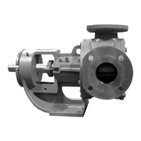
The provided manual describes the Viking Pump Jacketed Asphalt Pumps, specifically Series 34 and 434, available in HL, KK, LQ, Q, M, and N sizes. These pumps are designed for handling asphalt and other viscous liquids that require temperature control to maintain fluidity.

Function Description:

The Viking Jacketed Asphalt Pumps are positive displacement pumps, meaning they move a fixed amount of fluid with each revolution of their pumping elements. This design ensures consistent flow regardless of pressure changes. The "jacketed" feature indicates that the pump casing and head are equipped with a jacket, allowing for the circulation of a heating medium (such as steam or hot oil) to maintain the temperature of the asphalt or other viscous liquid being pumped. This is crucial for preventing the liquid from solidifying or becoming too viscous to pump efficiently, especially during startup or in cold environments.

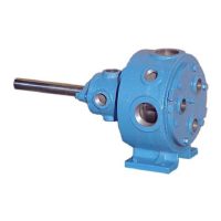
The pumps utilize a rotor and idler gear mechanism. The rotor, driven by an external power source, meshes with the idler gear, creating a pumping action. As the gears unmesh, a void is created, drawing liquid into the pumping chamber (suction side). As the gears mesh again, the liquid is displaced and forced out through the discharge port. The shaft rotation determines which port acts as suction and which as discharge; the port where the gear teeth come out of mesh is the suction port.

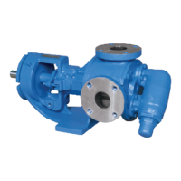
Pressure relief valves are an integral safety feature for these positive displacement pumps. Since they move a fixed volume of fluid, blocking the discharge line without pressure protection can lead to excessive pressure buildup, potentially damaging the pump or piping. The manual highlights that these pumps must be provided with some form of pressure protection, which can be a relief valve mounted directly on the pump, an in-line pressure relief valve, a torque limiting device, or a rupture disk. If pump rotation can be reversed, pressure protection must be provided on both sides of the pump. The relief valve adjusting screw caps should always point towards the suction side. It's important to note that relief valves are not designed to control pump flow or regulate discharge pressure.

The pumps can be configured with either packed glands or mechanical seals to prevent leakage around the shaft. Packed pumps use packing rings compressed by a packing gland, while mechanical seal pumps employ a more advanced sealing mechanism. The manual details specific instructions for both types of seals, including their installation and maintenance.

Usage Features:

The Viking Jacketed Asphalt Pumps are designed for long, trouble-free service under a wide variety of application conditions. However, proper installation and operation are critical for optimal performance and safety.

Key usage considerations include:

  • Rotation: The pumps operate equally well in clockwise or counter-clockwise rotation. The direction of shaft rotation dictates the suction and discharge ports.
  • Temperature Control: The jacketed design allows for precise temperature control of the pumped liquid, essential for handling asphalt and other temperature-sensitive viscous fluids. This prevents product solidification and ensures smooth operation.
  • Pressure Protection: As positive displacement pumps, they require external pressure protection. Users must ensure that a relief valve or other protective device is correctly installed and configured.
  • Drive System: The pump's driving means (motor, turbine, engine) must be properly "locked out" or made non-operational before any work is done on the pump to prevent accidental startup.
  • Liquid Compatibility: Users must be aware of the liquid the pump is handling and take necessary precautions, including consulting Material Safety Data Sheets (MSDS) to understand safe handling procedures.
  • Piping: Suction and discharge piping must be correctly connected, fully supported, and aligned with the pump. The pump should not be operated if piping is not connected.
  • Cleanliness: Maintaining a clean pump is good practice, as it facilitates inspection, adjustment, and repair, and helps prevent lubrication omissions due to hidden fittings.
  • Storage: If the pump is to be stored for an appreciable length of time, it should be drained, and internal parts should be coated with lubricating and preservative oil. All steam jacket chambers must be drained to prevent freezing.

Maintenance Features:

The manual emphasizes a minimum of maintenance for these pumps, but highlights several critical aspects:

  • Lubrication: External lubrication of all fittings with multi-purpose grease (NLGI #2) is recommended every 500 hours of operation. Over-greasing should be avoided. Applications involving very high or low temperatures may require specialized lubrication, and consultation with the factory is advised.
  • Packing Adjustment (for packed pumps): New packed pumps typically require initial packing adjustment as the packing "runs-in" to control leakage. Occasional inspection will determine the need for further adjustments or replacement. The packing gland must enter the stuffing box by at least one-eighth of an inch after tightening the nuts, ensuring the packing does not wedge between the stuffing box and the gland.
  • End Clearance Adjustment: After extended operation, pump performance can sometimes be improved by adjusting the end clearance. This involves carefully selecting the correct amount of head gaskets to ensure the pump turns freely with no appreciable endplay. The manual provides a gasket table with normal amounts used for different pump models.
  • Cleaning: Keeping the pump clean facilitates inspection, adjustment, and repair, and helps ensure proper lubrication.
  • Thrust Washers: For Q, M, and N size pumps, rotor thrust washers and rotor bearing sleeve thrust washers should be removed, examined for excessive wear, and replaced if necessary. These are located on the rotor hub and the casing end of the rotor bearing sleeve.
  • Wear Parts Inspection: The rotor-bearing sleeve, casing, or idler bushing should be inspected for wear and replaced if necessary. During major repairs, it is advisable to install a new head and idler.
  • Mechanical Seal Maintenance: For mechanical seal pumps, specific instructions are given for installation, including ensuring the shaft is clean and free of burrs, proper placement of setting clips (for X-100 & X-200 seals) or rotation of installation tabs (for PSII® seals), and tightening of nuts and setscrews. Venting air from the stuffing box before startup is crucial to prevent premature seal failure. Preheat the seal before introducing hot product, and consider continuous flow steam quench on the atmospheric side to prevent premature seal failure. For double seals, the seal chamber must be pressurized before startup. The pump should not be started until fully heated, as hard product in the seal chamber can cause instant failure.
  • Disassembly and Assembly: The manual provides detailed steps for disassembly and assembly, including cautions against damaging the idler, head gasket, and rotor bearing sleeve bushing. It emphasizes marking the head and casing before disassembly to ensure proper reassembly and correct positioning of the idler pin.
  • Safety Precautions: Throughout the manual, significant emphasis is placed on safety. Before opening any liquid chamber, users must ensure that all pressure is vented, the driving means is locked out, and they are aware of the liquid being handled and necessary precautions (MSDS). Failure to follow these measures can result in serious injury or death. Guards for drive equipment must be in place before starting the pump.

Viking pump Q34 Specifications

General IconGeneral
TypePositive Displacement
SeriesQ34
Seal TypeMechanical Seal
MaterialStainless Steel
ApplicationsChemical Processing, Food Processing

Related product manuals