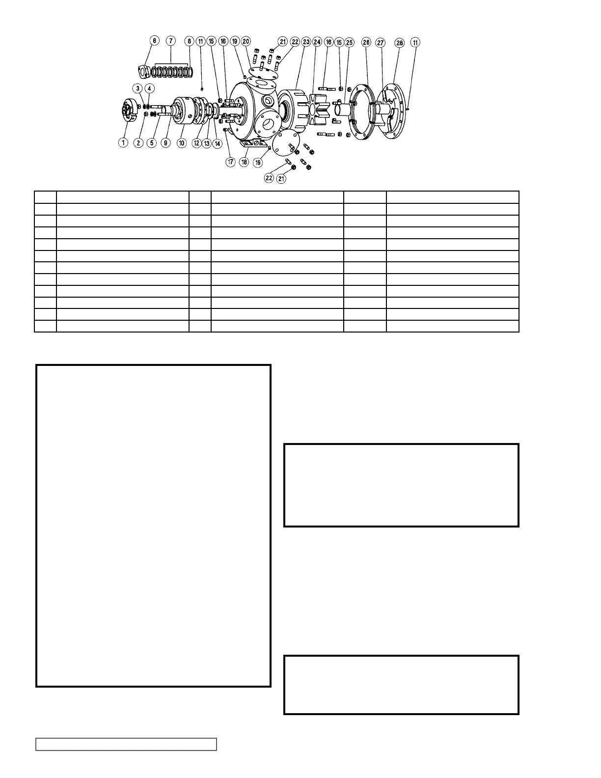
FIGURE 8
EXPLODED VIEW
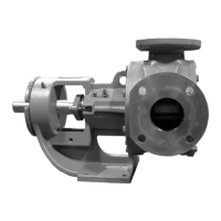
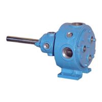
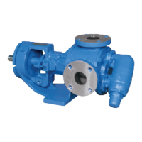
SERIES 34 & 434 PUMPS (N SIZE)
ITEM NAME OF PART ITEM NAME OF PART ITEM NAME OF PART
1 Mechanical Seal 12 Gasket 23 Rotor and Shaft Assembly
2 Nut 13 Thrust Washer, Rotor Bearing Sleeve 24 Idler and Bushing Assembly
3 Lockwasher 14 Thrust Washer, Rotor 25 Idler Bushing
4 Flat Washer 15 Nut 26 Head Gasket Set
5 Stud 16 Stud 27 Idler Pin
6 Packing Gland 17 Pipe Plug 28 Head (Jacketed) and Idler Pin Assembly
7 Packing 18 Casing (Jacketed) Not Illus. Relief Valve
8 Packing Retainer Washer 19 Pipe Plug Not Illus. Relief Valve Gasket
9 Rotor Bearing Sleeve Bushing 20 Gasket Not Illus. Relief Valve Capscrews
10 Rotor Bearing Sleeve 21 Nut
11 Pipe Plug 22 Stud
SECTION TSM 430 ISSUE d PAGE 6 OF 9
DISASSEMBLY
DANGER !
Before opening any Viking pump liquid
chamber (pumping chamber, reservoir,
relief valve adjusting cap fitting, etc.)
Be sure:
1. That any pressure in the chamber has
been completely vented through the
suction or discharge lines or other
appropriate openings or connections.
2. That the driving means (motor, turbine,
engine, etc.) has been “locked out” or
made non-operational so that it cannot
be started while work is being done on
pump.
3. That you know what liquid the pump
has been handling and the precautions
necessary to safely handle the liquid.
Obtain a material safety data sheet
(MSDS) for the liquid to be sure these
precautions are understood.
Failure to follow above listed
precautionary measures may result in
serious injury or death.
NOTE: Mark the head and casing before disassembly to
insure proper reassembly. The idler pin, which is offset in
pump head, should be properly positioned toward and equal
CAUTION !
Do not allow the idler to fall from the idler
pin. Tilting the head up as it is removed will
prevent this occurrence. Avoid damaging
the head gasket if possible.
CAUTION !
Avoid damaging the rotor bearing sleeve
bushing.
3. For pumps with X-100 or X-200 mechanical seals, insert
the setting clips back in place. For pumps with PSII®
seals, rotate the installation tabs 90 degrees so they
contact the sleeve. Loosen the set screws that secure
the seal sleeve to the shaft.
4. Remove the nuts, washers and lockwashers holding the
mechanical seal and slide the seal assembly from the
shaft.
5. Carefully remove rotor and shaft from the pump.
distance between the port connections to allow for proper
flow of liquid through the pump.
1. Allow pump to cool. Remove the head from the pump.
If pump is furnished with a relief valve it need not be
removed from head or disassembled at this point.
2. For mechanical seal pumps, remove any flush lines
going to the mechanical seal if this has not already been
done.