EasyManua.ls Logo

Viking pump HJ4195 User Manual

Default Icon
10 pages
To Next Page IconTo Next Page
Page #1 background imageLoading...
Page #1 background image
SECTION TSM 144
PAGE 1 OF 10
ISSUE F
VIKING PUMP, INC. x A Unit of IDEX Corporation xCedar Falls, IA 50613 USA
TECHNICAL SERVICE MANUAL
CONTENTS
INTRODUCTION
The illustrations used in this manual are for identification
purposes only and cannot be used for ordering parts. Obtain a
parts list from the factory or a Viking® representative. Always
give complete name of part, part number and material with
model number and serial number of pump when ordering
repair parts. The unmounted pump or pump unit model
number and serial number are on the nameplate.
In the Viking model number system, basic size letters are
combined with series number (4195 and 495) are used to
indicate either an unmounted pump or mounted pump unit.
FIGURE 1
G, GG, H, HJ and HL4195 SERIES
Foot Type Unmounted Pump with Tapped Ports
Introduction . . . . . . . . . . . . . . . . . . . . . . . 1
Safety Information....................2
Special Information . . . . . . . . . . . . . . . . . . . 3
Special Mechanical Seals................3
Maintenance . . . . . . . . . . . . . . . . . . . . . . 3
Disassembly . . . . . . . . . . . . . . . . . . . . . . 4
Assembly . . . . . . . . . . . . . . . . . . . . . . . . 7
Thrust Bearing Adjustment . . . . . . . . . . . . . . . 8
Installation of Carbon Graphite Bushings ........8
Pressure Relief Valve Instructions . . . . . . . . . . . 9
FIGURE 2
AS, AK and AL4195 SERIES
Foot Type Unmounted Pump with Tapped Ports
FIGURE 3
G, GG, H, HJ and HL495 SERIES
Unmounted Pump with Tapped Ports
UNMOUNTED PUMP UNITS
Foot Mounted
Units are designated by the
unmounted pump model
numbers followed by a letter(s)
indicating drive style.
D = Direct Drive
G4195 HL4195
GG4195 AS4195
H4195 AK4195
HJ4195 AL4195
Flange Mounted
M = Horizontal Direct Drive
G495 HL495
GG495 AS495
H495 AK495
HJ495 AL495
This manual deals only with Series 4195 and 495 Heavy
Duty Pumps. Refer to Figures 1 through 14 for general
configuration and nomenclature used in this manual. Pump
specifications and recommendations are listed in Catalog
Section 144, Series 4195 and 495 Heavy Duty Pumps.
FIGURE 4
AS, AK and AL495 SERIES
Unmounted Pump with Tapped Ports
Electronic copies of the most current TSM issue can be found on the Viking Pump website at www.vikingpump.com
HEAVY-DUTY PUMPS
SERIES 4195 AND 495
SIZES G, GG, H, HJ, HL, AS, AK, AL
Question and Answer IconNeed help?

Do you have a question about the Viking pump HJ4195 and is the answer not in the manual?

Viking pump HJ4195 Specifications

General IconGeneral
BrandViking pump
ModelHJ4195
CategoryWater Pump
LanguageEnglish

Summary

Introduction to Viking Pump Series 4195 and 495

Pump Model Numbering System

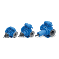
Explains how Viking model numbers combine size letters with series numbers.

Illustrations for Identification Purposes

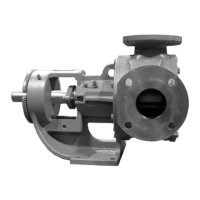
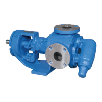
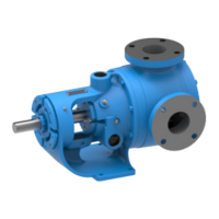
Illustrations in the manual are for identification, not for ordering parts.

Safety Information and Instructions

General Safety Precautions and Symbols

Details safety symbols (Danger, Warning) and essential precautions before operating the pump.

Special Information and Maintenance

Pressure Relief Valves

Details requirements for pressure protection and relief valve placement.

Special Mechanical Seals

Information on standard and non-standard mechanical seals and PTFE seals.

Pump Maintenance Guidelines

Covers pump cleaning, storage, and suggested repair tools.

Pump Disassembly Procedure

Disassembly Steps and Precautions

Step-by-step guide for pump disassembly, including safety warnings and part identification.

Pump Assembly

Standard Mechanical Seal Installation

Detailed steps for installing the standard mechanical seal on the pump shaft.

General Assembly Steps

Covers cleaning parts, bearing lubrication, rotor/shaft installation, and head assembly.

Thrust Bearing Adjustment and Bushing Installation

Thrust Bearing Adjustment Procedure

Procedure for adjusting pump end clearance and setting thrust bearing assembly.

Installation of Carbon Graphite Bushings

Guidelines for installing carbon graphite bushings, emphasizing care and using a press.

Pressure Relief Valve Instructions

Relief Valve Disassembly and Assembly

Steps for disassembling and reassembling the pressure relief valve.

Pressure Relief Valve Adjustment

Adjustment Procedure and Important Notes

Instructions for adjusting pressure relief valve settings and ordering parts.

Related product manuals