SECTION TSM 144 ISSUE F PAGE 5 OF 10
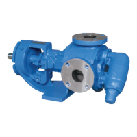
FIGURE 7 - EXPLODED VIEW FOR MODELS G, GG, H, HJ AND HL 4195 AND 495
ITEM NAME OF PART ITEM NAME OF PART ITEM NAME OF PART
1 Locknut 8 Casing (4195) 14 Head O-Ring
2 Snap Ring (Outer) 8A Casing (495) 15 Idler Pin
3 Ball Bearing (Outer) 9 Pipe Plug 16 Head and Idler Pin Assembly
4 Snap Ring for Shaft * 10 Mechanical Seal 17 Capscrew for Head
5 Bearing Housing 11 Rotor and Shaft Assembly 18 Gasket for Relief Valve
6 Snap Ring (Inner) 12 Idler Bushing 19 Relief Valve
7 Ball Bearing (Inner) 13 Idler and Bushing Assembly 20 Capscrew for Valve
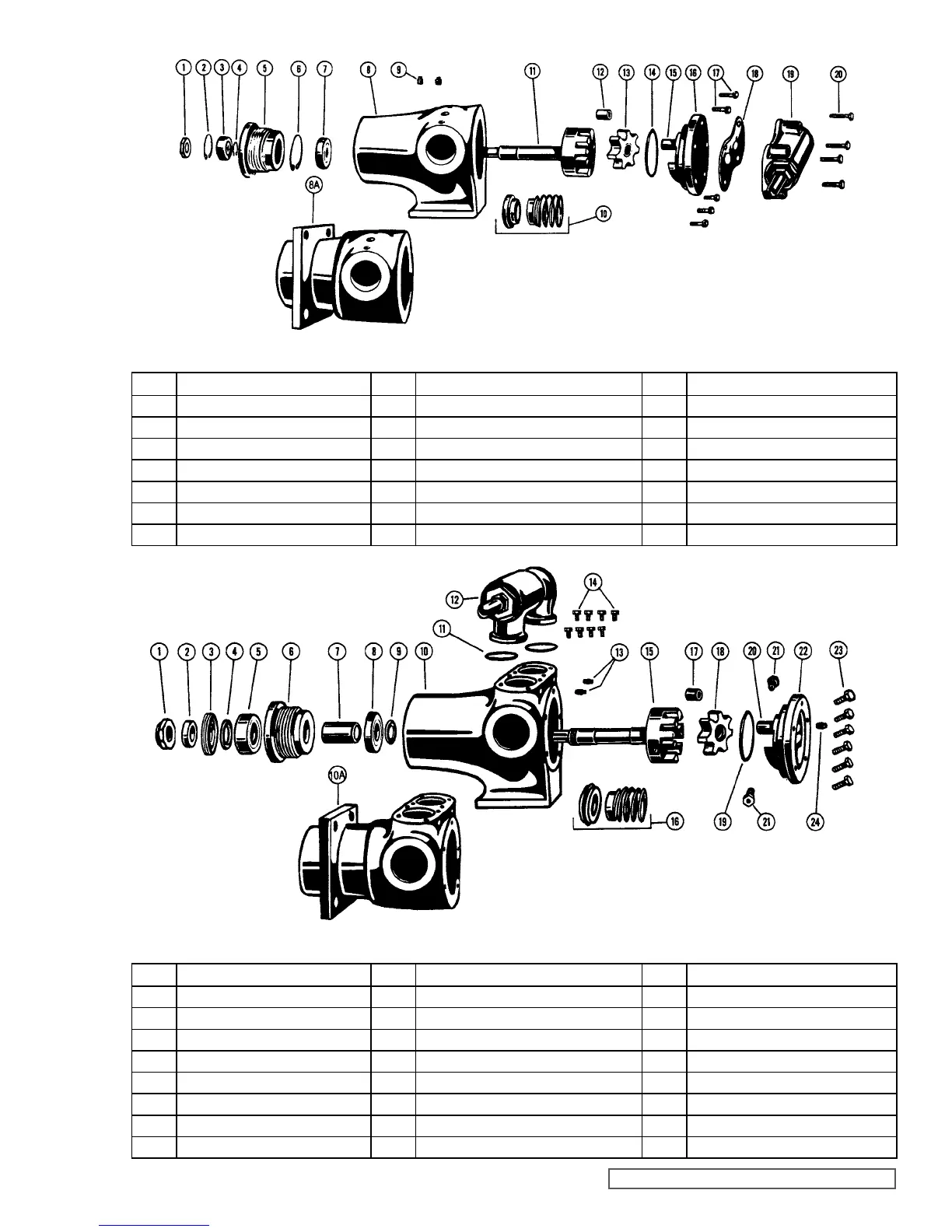
ITEM NAME OF PART ITEM NAME OF PART ITEM NAME OF PART
1 Locknut 9 Bearing Retainer Washer 16 Mechanical Seal
2 Bearing Spacer Collar 10 Casing (4195) 17 Idler Bushing
3 End Cap for Bearing Housing 10A Casing (495) 18 Idler and Bushing Assembly
4 Lip Seal for Bearing Housing 11 O-Rings for Relief Valve 19 Head O-Ring
5 Ball Bearing (Outer) 12 Relief Valve 20 Idler Pin
6 Bearing Housing 13 Pipe Plug 21 Check Valve
7 Bearing Spacer 14 Capscrew for Valve 22 Head and Idler Pin Assembly
8 Ball Bearing (Inner) 15 Rotor and Shaft Assembly 23 Capscrew for Head
Modifications to the pump casing and rotor are required for installation
of optional PTFE mechanical seal. Consult the factory.
Modifications to the pump casing and rotor are required for installation
of optional PTFE mechanical seal. Consult the factory.
FIGURE 8 - EXPLODED VIEW FOR MODELS AS, AK AND AL 4195 AND 495
* Not used on G & GG size pumps.