5.0 AFFF SCHEMATIC
IMPORTANT FOR OPERATION:
Piping between the concentrate vessel and concentrate controller is not furnished by the Concentrate Control System
manufacturer. The concentrate piping to the controller must meet certain criteria to prevent loss of concentrate into the
water supply piping. This piping (dotted lines on the schematic below) is to be included by the design engineer for the
type of system wanted - manual, electrical, pneumatic, fail-safe, etc. Viking does not accept responsibility for concentrate
piping to the controller or water piping to the concentrate vessel.
NOTE: (Per schematic below) Manual System - Valve No.’s 1 and 2 must be opened manually.
Automatic System - Valve 10 must be opened with an alarm signal
(if necessary, use manual override).
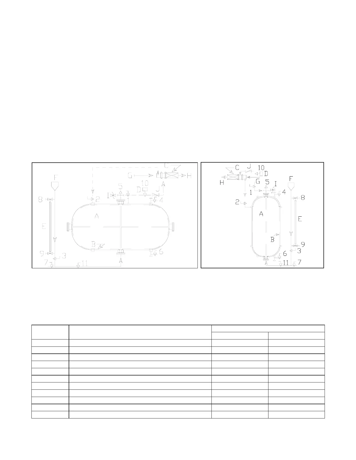
TYPICAL SCHEMATIC DIAGRAMS:
Consult the system design for actual piping requirements. Before filling system, consult manufacturers filling
procedure. Improper filling can result in damage to the concentrate bladder.
HORIZONTAL VERTICAL
COMPONENT DESCRIPTION E - Sight Gauge
A - Storage Tank F - Fill Cup
B - Bladder G - Water Supply Piping (See instructions above)
C - Concentrate Controller H - Solution Delivery Piping (See instructions above)
D - Automatic Valve (optional) I - Thermal Relief Valve (Optional)
(See instructions above) J - Swing Check Valve
VALVE
DESCRIPTION
*NORMAL VALVE POSITION
NUMBER Automatic System Manual System
1 Manual concentrate shut-off - by others N.O. N.C.
2 Water pressure shut-off - by others N.O. N.C.
3 Fill cup shut-off N.C. N.C.
4 Tank water vent N.C. N.C.
5 Diaphragm concentrate vent N.C. N.C.
6 Water drain/fill N.C. N.C.
7 Concentrate drain/fill N.C. N.C.
8 Upper sight gauge \ Open only when N.C. N.C.
9 Lower sign gauge / system is depressurized. N.C. N.C.
10 Automatic concentrate isolation (Optional) by others N.C. -
11 Fill line master shut-off N.C. N.C.
* N.O. - Normally Open N.C. - Normally Closed
5