TECHNICAL DATA
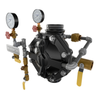
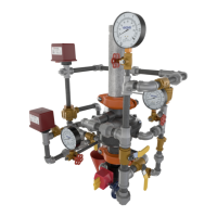
2” MODEL G-2000 DRY VALVE
RISER ASSEMBLY
Page 2 of 13
The Viking Corporation, 210 N Industrial Park Drive, Hastings MI 49058
Telephone: 269-945-9501 Technical Services: 877-384-5464 Fax: 269-818-1680 Email: techsvcs@vikingcorp.com
Visit the Viking website for the latest edition of this technical data page www.vikinggroupinc.com.
Form No. F_011110 17.04.27 Rev 17.1
B. Air Supply Design
Calculating Trip Pressure and Air Compressor Size
To calculate the point where the water pressure will overcome the air pressure and trip the valve, divide the static system water pres-
sure by the differential (Approximately 5.75:1).
Example:
Static Water Pressure = 64 psi (4.4 bar) → Trip Point = 64 / 5.75 = 11 psi (0.76 bar).
The dry valve will trip when the air pressure is reduced to 11 psi (0.76 bar).
NFPA 13 requires that the air supply be capable of lling the entire sprinkler system to its required air pressure within 30 minutes. A
common method of sizing an air compressor is to use the following formula:
Compressor Size (cfm) = 0.012 x V (gal)
Where V = System volume and 0.012 is a common multiplier that will provide 40 psi (2.8 bar) in 30 minutes.
The following formula may be used for air pressures different than 40 psi (2.8 bar):
Where:
V = Volume
P = Required Air Pressure (Trip Pressure + 15 psi)
T = Fill time (typically 30 min.)
7.48 = gal. / ft.
3
14.7 = atmospheric pressure
Compressor
Size (cfm) =
V x P
7.48 x 14.7 x T
Example:
System volume as determined by table 1 = 750 gallons
System water pressure = 73 psi (5 bar)
Required air pressure = (73/5.75) + 15 = 28 psi (1.93 bar)
Compressor Size (cfm) =
(750 x 28)
= 6.4 cfm
7.48 x 14.7 x 30
Therefore, the compressor shall be capable of providing 7 cfm.
D. Pressure Switch Wiring;
Wire the Alarm Pressure Switch (PS10) and Air Superviso-
ry Switch (PS40), and adjust pressure settings as shown in
Figures 3 - 5.
Table 1 - Pipe Capacity for Sizing Air Compressors
Pipe Diameter Capacity
US International
Schedule 40 (1” to 6”)
Schedule 30 (8”)
Schedule 10
Gal / Ft L / m Gal / Ft L / m
1” DN25 0.045 0.559 0.049 0.608
1-1/4” DN32 0.078 0.969 0.085 1.043
1-1/2” DN40 0.106 1.316 0.115 1.428
2” DN50 0.174 2.161 0.190 2.360
2-1/2” DN65 0.248 3.080 0.283 3.515
3” DN80 0.383 4.756 0.434 5.390
3-1/2” DN90 0.513 6.370 0.577 7.165
4” DN100 0.660 8.196 0.740 9.190
5” DN125 1.040 12.915 1.144 14.206
6” DN150 1.501 18.640 1.649 20.477
8” DN200 2.660 33.032 2.776 30.472
For Metric Units 1 Ft. = 0.3048 M, 1 Gal. = 3.785L
Table 2 - Air Pressure Settings
Maximum Water
Pressure
Air Pressure Setting
Minimum Maximum
psi bar psi bar psi bar
50 3.4 22 1.5 27 1.8
75 5.1 26 1.8 31 2.1
100 6.8 30 2.0 35 2.4
125 8.6 34 2.3 39 2.6
150 10.3 38 2.6 43 2.9
175 12.0 42 2.8 47 3.2
200 13.7 45 3.1 50 3.4
225 15.5 49 3.4 54 3.7
250 17.2 53 3.6 58 3.9
Supervisory Pressure Switch should be set 5 psi
(0.34 bar) below air compressor cut out.
Table 3 - Quick Reference Compressor Size
Compressor
Size (HP)
Free Air @ 40 psi
(2.8 bar) (cfm)
Maximum Gallons in
System to Pump to 40 psi
(2.8 bar) in 30 Minutes
1/6 1.0 90
1/3 2.0 180
1/2 3.1 300
1 5.9 600
 Loading...