95
DEFRNLIT EN
0478 131 9923 B - EN
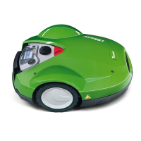
9.1 Notes on initial installation
An installation assistant is
available for installation of the
robotic mower. This program
guides you through the entire
initial installation process:
● Setting the language, date and time
● Installing the docking station
● Routing the perimeter wire
● Connecting the perimeter wire
● Linking the robotic mower and docking
station
● Checking installation
● Programming the robotic mower
● Completing initial installation
The installation assistant must be worked
through in its entirety. Only then is the
robotic mower ready for operation.
Preparatory measures:
● Mow the lawn using a conventional
lawn mower prior to initial installation
(ideal grass height of 3 to 4 cm).
● In the case of a hard and dry surface,
water the mowing area lightly in order to
make it easier to drive in the fixing pins.
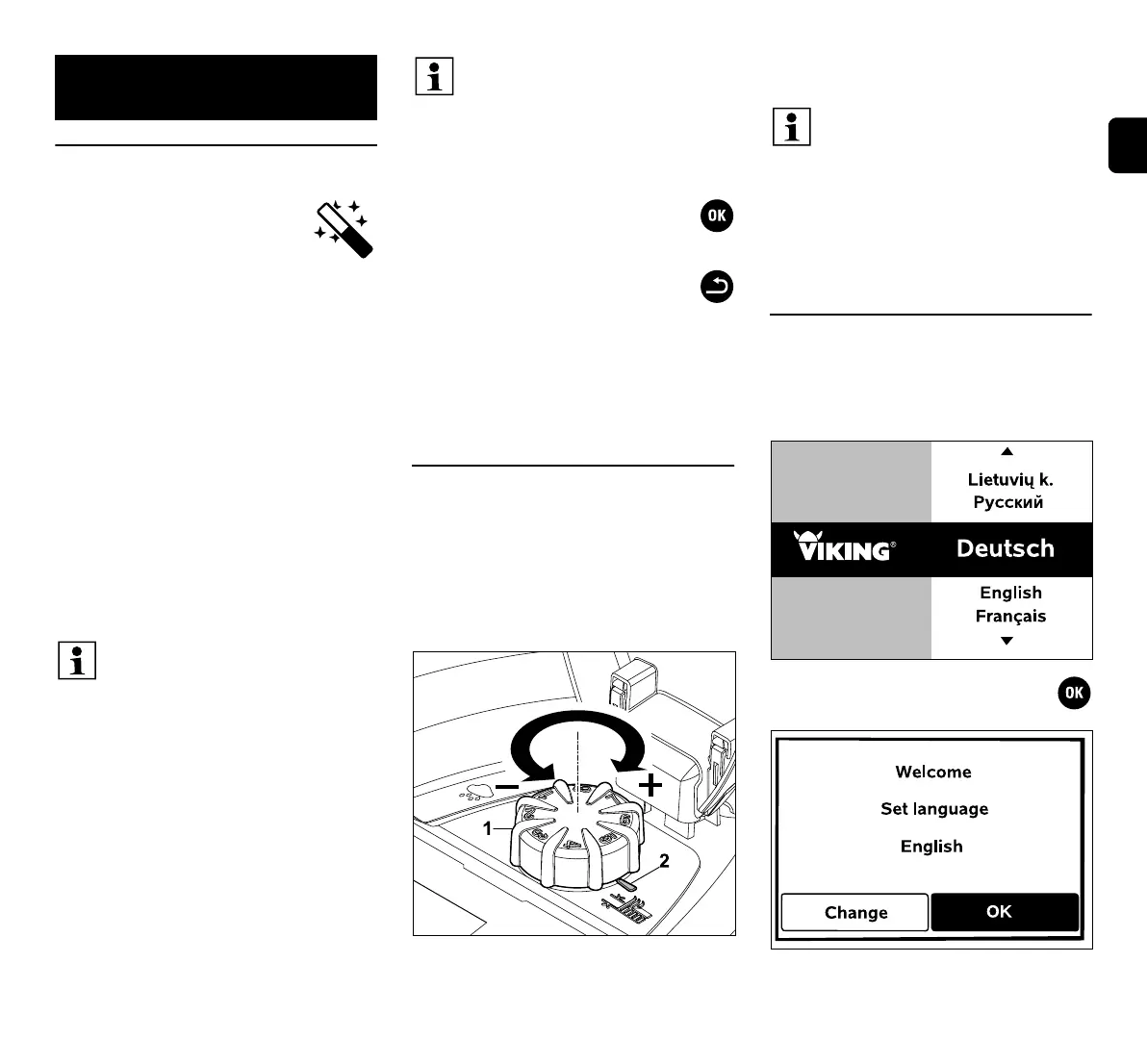
9.2 Adjusting the cutting height
Lowest cutting height:
Level 1 (20 mm)
Highest cutting height:
Level 8 (60 mm)
– Open flap. (Ö 14.2)
Turn the rotary knob (1). The marking (2)
indicates the set cutting height.
9.3 Setting the language, date and time
● Pressing any button on the display
activates the machine and thus the
installation assistant.
Select the required display language
and confirm with the OK button.
9. Initial installation
The installation assistant is re-
activated following a reset (reset to
factory defaults). (Ö 10.17)
When navigating through the
menus, follow the instructions in the
section entitled "Operating
instructions". (Ö 10.1)
You can select options, menu items
and buttons using the control pad.
You can open submenus and
confirm selections using the
OK button.
Use the Back button to
leave the active menu or
jump one step back in the
installation assistant.
If errors or faults occur during the
initial installation, a corresponding
message appears in the display.
(Ö 23.)
The rotary knob can be removed
upwards from the adjustment
element. This design serves a
safety function (it ensures that the
machine cannot be lifted and
carried by the rotary knob) and to
prevent the cutting height from
being modified by unauthorised
persons.
 Loading...