TECHNICAL DATA
Page 2 of 4
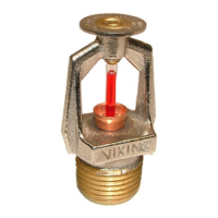
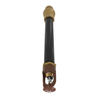
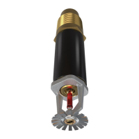
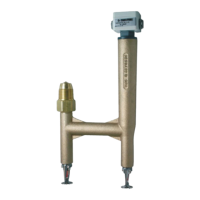
MICROFAST HP
FIXED TEMPERATURE
RELEASE VK800
The Viking Corporation, 210 N Industrial Park Drive, Hastings MI 49058
Telephone: 269-945-9501 Technical Services 877-384-5464 Fax: 269-818-1680 Email: techsvcs@vikingcorp.com
Form No. F_051091 18.10.25 P65
fixed temperature releases as directed by installation standards.
3. Select the proper temperature-rated fixed temperature releases and sprinklers for the hazard and ambient temperatures involved.
NFPA 13 requires the activating temperature of the release system to be lower than the activating temperature of the sprinkler
system.
a. Normally, it is advisable to use the lowest temperature combinations approved for the hazard and ambient temperature in-
volved, as this permits early detection and more rapid attack.
B. Spacing:
1. Refer to the Approval Chart on this page (except for deluge systems) for listed spacing of fixed temperature releases below 15 ft.
smooth, flat, horizontal ceilings. Reduced spacing may be required for other ceiling configurations.
2. For spacing of fixed temperature releases on deluge systems, comply with spacing guidelines set forth in NFPA 72.
3. To meet FM requirements, space fixed temperature releases according to guidelines set forth in NFPA 13 and FM recommenda-
tions.
4. The distance between adjacent fixed temperature releases is not to exceed the listed spacing.
5. The distance between a fixed temperature release and any wall or partition that extends to within 18” (457 mm) of the ceiling is
not to exceed ½ the listed spacing.
6. The distance from the fixed temperature release to all points in the area of coverage (corners) is not to exceed 70 percent of the
listed spacing.
C. Location:
1. When applying NFPA 72, Viking MicrofastHP® Fixed Temperature Releases are treated as spot-type heat detectors. Locate fixed
temperature releases between 4” and 12” (100 mm and 300 mm) below the ceiling, and no closer than 4” (100 mm) from any wall
or partition that extends to within 18” (457 mm) of the ceiling.
a. In the case of solid joist construction, fixed temperature releases shall be mounted at the bottom of joists.
b. In the case of beam construction where beams are less than 12” (300 mm) in depth and less than 8 ft. (2,4 m) on center, fixed
temperature releases may be installed on the bottom of beams.
2. Fixed temperature releases are listed for installation in any position. When installing fixed temperature releases on release piping
subject to freezing, install them in the upright position only.
II. Installation
WARNING: The Viking MicrofastHP® Fixed Temperature Release is manufactured and tested to meet the rigid requirements
of approving agencies. The xed temperature release is designed to be installed in accordance with recognized installation
standards. Deviation from the standards or any alteration to the xed-temperature release after it leaves the factory includ-
ing, but not limited to: painting, plating, coating, or modication, may render the device inoperative and would automatically
nullify the approval and any guarantee made by The Viking Corporation.
TABLE 1: AVAILABLE TEMPERATURE RATINGS, FINISHES AND APPROVALS
Temperature
Classification
Nominal
Temperature Rating
Maximum Ambient
Ceiling Temperature
1
Bulb Color
Temperature
Rating Color
Code
Listed Spacing
3
Ordinary 135° F (57° C) 100 °F (38 °C) Orange None 40’ x 40’ (12m x 12m)
Ordinary 155° F (68° C) 100 °F (38 °C) Red None 20’ x 20’ (6,1m x 6,1m)
Intermediate 175° F (79° C) 150 °F (65 °C) Yellow White 40’ x 40’ (12m x 12m)
Intermediate 200° F (93° C) 150 °F (65 °C) Green White 20’ x 20’ (6,1m x 6,1m)
High 286° F (141° C) 225° F (107° C) Blue Blue 20’ x 20’ (6,1m x 6,1m)
Finishes: Brass, Chrome-Enloy®, White Polyester and black Teon®
2
Footnotes
1
Based on NFPA-13. Other limits may apply, depending on fire loading, release location, and other requirements of the Authority Having Jurisdiction.
Refer to specific installation standards.
2
The corrosion-resistant coatings have passed the standard corrosion test required by the listed approving agencies. These tests cannot and do not
represent all possible corrosive environments. Prior to installing, verify through the end-user that the coatings are compatible with or suitable for the
proposed environment. The coatings indicated are applied to the exposed exterior surfaces only and, therefore, cannot be used as open releases.
Note that the spring is exposed on the Teflon® and Polyester-coated releases.
3
Listed spacings are for smooth, flat, horizontal ceilings. Installation must comply with NFPA 13.
 Loading...