5
SL24.T
EN
Controllable actuators
Ref. Description
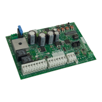
ESM2 ACTO 600D 24 V 600 kg sliding gate actuator w/ Dip & Trimmer control panel
Trimmer function
Trimmer Description
FM1 Power of motor (adjusts the torque of motor, turn the trimmer clockwise to increase the force)
VS Slow-down speed (adjusts the slow-down speed of the motor, turn the trimmer clockwise to increase the speed)
V Standard speed (adjusts the standard speed of the motor, turn the trimmer clockwise to increase the speed)
TCA Automatic re-closing time (adjustable from 2 to 120 seconds, turn the trimmer clockwise to increase the time)
Button functions
Button Description
PROG Button for programming the travel
MRX Button for programming or deleting remote controls
51 Step-by-step command button
DIP-switch functions
Dip Function Status Description
DIP 1 Automatic closing
OFF Automatic closing o
ON Automatic closing on
DIP 2 Apartment block
OFF Apartment block o
ON
Apartment block on (while the gate is opening, you cannot stop the movement with a radio command or with inputs
51 (step-by-step) and 52 (pedestrian). With automatic closing on (DIP 1 = ON) and the gate open, an additional
step-by-step command (terminal 51 or radio command) renews the pause time, and if input 51 remains engaged,
the control panel suspends the pause count until the input is disengaged (for connecting any coils or a timer)
DIP 3 Pre-ash
OFF Pre-ashing o
ON Pre-ashing on, before the gate moves the ashing light comes on for 3 seconds
DIP 4 Input 63 type
OFF Input 63 is for internal photocell
ON Input 63 is for safety edge (see DIP 7 for the safety edge type)
DIP 5 Photo test
OFF Photo-test function o
ON
Photo-test on: the negative accessory power supply terminal (0) turns o for a few fractions of a second before the
start of movement, so any accessories that require a permanent power supply (e.g. photocell receivers) must get
the negative power supply from an input common (terminal 99).
DIP 6 Output 12
OFF
Output 12 for Courtesy Light (LCO): each time the gate moves, the output remains on for 100 s.
The remote control buttons saved on the second radio channel give a pedestrian command
ON
Output 12 for Auxiliary Radio output: the remote control buttons saved on the second radio channel turn the output
on for 1 s
DIP 7 Safety edge type
OFF Sensitive edge with normally closed contact
ON Resistive sensitive edge, normally open contact with balancing resistance of 8.2 K Ohm in parallel
DIP 8 Rapid closing
OFF Fast closing o
ON
Fast closing function on: if the closing photocell (terminal 62) is engaged, the automatic closing time is set to 5
seconds when it is released
DIP 9 Not used
DIP 10
Opening
direction
OFF Gate opening to the left
ON Gate opening to the right
LED functions
LED Status Description
PWR
OFF Mains power supply not present
ON Mains power supply present
PRG
(or ashing light)
2 blinks Photocell test failed (incorrect wiring or photocells busy)
3 blinks Problem detected in the circuit that activates motor
4 blinks Problem on encoder (encoder damaged or wired incorrectly)
5 blinks Serious EEPROM error (EEPROM missing or damaged)
6 blinks Motor timeout (gear motor not engaged or damaged)
7 blinks Fuse F2 blown
8 blinks Motor overcurrent error
9 blinks Inverted motor power supply cables (terminals 21-22)
ENCA
OFF When the motor is operating: rst encoder channel signal absent (encoder not working)
ON
When the motor is operating: rst encoder channel present (it ashes very fast, depending on the motor rotation
speed)

 Loading...