EasyManua.ls Logo

Vimar ELVOX RS02 - User Manual

Vimar ELVOX RS02
144 pages
Go to English
To Next Page IconTo Next Page
Loading...
Manuale per il collegamento e l’uso - Connection and operating manual
Manuel de raccordement et d’utilisation - Manual de instrucciones para la conexión y el uso
Anschluss- und Bedienungsanleitung - Εγχειρίδιο σύνδεσης και χρήσηςL
RS02
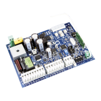
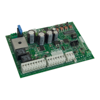
Centrale con display 12 Vdc per cancelli scorrevoli e barriere stradali
Control panel with display 12 Vdc for sliding gates and road barriers
Centrale avec afficheur 12 Vcc pour portails coulissants et barrières routières
Central con pantalla de 12 Vcc para cancelas correderas y barreras de carretera
Steuergerät 12 Vdc mit Display für Schiebetorantrieb und Straßensperren
Κεντρική μονάδα με οθόνη 12 Vdc για συρόμενη καγκελόπορτα και οδοφράγματα
CN8
IBRIDO RX
CN1
SEC
CN7
VA2
VA1
ELVOX SERIE EC
PT1
25 26
FSC
FST
APM1
CHM
1
2CA
N
COM2
AUX
+VA
-VA
-LAM
P
+LAMP
COM1
APC
H
APED
COM1
STOP
FOTO
STPA
FCAP
COM1
FCCH
ENC
-
ANT
CN6
U1
CN2
CN3
APED
DL5DL10 DL6
CN4
FCAPAPCH
DL9
STOP
DL2
FOTO
DL3
STPA
DL1
FCCH
DL
DL
NC1M
NC
DL
NC1
SW1
PROGRAM. MENU'
23 24
CN11
CN9
U2
JP3
123456789 17 18 1910 11 12 13 14 15 16
AC
DL11
AP/CH
P1
P2 P5
P3
P4
OKESC
SE
- E
+ E
8
7
E
E
X
4
E
0
ON
12
D
20 A
F2 (ATO)
F1 (5x20)
T 3.15A

Table of Contents

Questions and Answers:

Vimar ELVOX RS02 Specifications

General IconGeneral
BrandVimar
ModelELVOX RS02
CategoryControl Panel
LanguageEnglish

Summary

Installer Safety Warnings and Precautions

Environmental and Disposal Guidelines (WEEE)

Product must be disposed of separately from normal household waste according to WEEE directive.

Hazardous Substance Information (WEEE)

Details risks associated with substances in electrical equipment and promotes proper waste collection.

Product Characteristics and Control Panel Overview

Control Panel Component Identification

Identifies key components of the control panel with numbered references and descriptions.

Risk Assessment for Gate;Barrier Operation

Electrical Wiring Harness Diagrams

System Setup: Power Supply and Accessory Wiring

Power Supply Line Connection

Describes the connection of the power supply line, including fuse details.

Wiring for Lights and Warning Signals

Details wiring for courtesy lights, warning lights, and accessory power supply.

Connecting Control Buttons and Safety Devices

Control Button and Key Switch Connections

Explains how to connect control buttons and key switches to the CN2 terminal.

Photocell Connections

Illustrates the wiring for connecting photocells to the control panel.

Advanced Safety Input Connections

Sensitive Edge Connection Types

Describes connections for switch and resistive sensitive edges.

Internal Photocell Configuration

Details the setup for connecting an internal photocell to the STPA input.

Specialized Input Functions

Photocell Photo-Test Function

Explains how to activate and connect photocells with the photo-test function.

Stop Button Wiring

Details the connection of a normally closed stop button.

Antenna Connection and Circuit Component Descriptions

LED Indicator Functions

Lists and describes the function of various LEDs on the circuit board.

Control Button Functions

Describes the operation of buttons like AP/CH, ESC, UP, DOWN, ENTER.

Actuator Type Configuration

Gate;Barrier Travel Programming

Quick Programming Procedure (LrnE)

Step-by-step guide for initial gate/barrier travel calibration.

Remote Control Management (RAD)

Saving Remote Controls

Procedure for saving remote controls to the control panel's memory.

Comprehensive Programming Menu Description

Main Menu Options Overview

Outlines the main options available in the programming menu.

Automatic Closing Time Adjustment

Detailed Programming Procedures

LRNE: Quick Travel Programming Steps

Detailed steps for LRNE quick programming for gate/barrier travel.

RAD: Remote Control Management Steps

Detailed steps for managing remote controls via the RAD menu.

Custom Travel Programming (LRN)

LRN Procedure Description

Guides on defining deceleration points for custom gate/barrier travel.

Parameter Adjustment (PAR) and Reference Table

Parameter Table Details

Provides a detailed list and description of all programmable parameters.

System Reset and Operation Counters

Default Parameter Reset (DEF)

Instructions for resetting all parameters to factory defaults.

Operation Counter Functions (CNT)

Explains how to view absolute and partial operation counters.

Troubleshooting and Security Features

Error Log and Fault Display (ERR)

Details how to view and clear the last 9 faults or errors.

Password Protection Setup (PASS)

Explains how to enable and manage password protection for menu access.

Programming Summary Flowchart

Quick Programming Flow

Visual flowchart for the quick programming sequence.

Remote Control Flow

Visual flowchart for remote control management operations.

Custom Programming Flow

Visual flowchart for custom gate/barrier travel programming.

Parameter Adjustment Flow

Visual flowchart for modifying system parameters.

Installation and Troubleshooting Guide

Battery Installation Procedure

Instructions for installing the backup battery circuit.

Common Troubleshooting Scenarios

Lists common problems and their solutions for system operation.

List of Programmable Parameters

Remote Control User Association Table

Control Card Installation with Optical Encoder

Motor, Sensor, and Encoder Wiring

Details wiring for electric motor, limit stop sensor, and encoder.

Opening Direction Adjustment

Explains how to adjust the gate/barrier opening direction using parameter P31.

EC Declaration of Conformity

Related product manuals