32
Contents
Previous
Page
First
Page
Next
Page
Previous
View
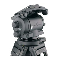
21 Install the ball clamp assembly as follows (Fig 6.4):
21.1 Screw the stud of the ball clamp assembly (5.1) into the pan base.
21.2 Install three grub screws (5.2) and tighten to lock the ball clamp assembly.
21.3 Install the bowl clamp (6).
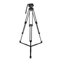
Pozi-loc tripod
General
22 The tripod legs are constructed using adhesive processes. The following procedures are the limit of
component replacement.
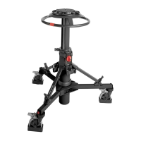
Replacing tripod legs
23 The legs are secured in the bowl assembly by pivot clamps. Each clamp is secured by a single screw.
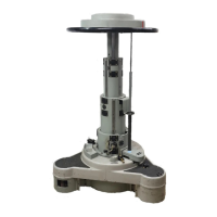
Removal
24 Remove the tripod leg as follows (Fig 6.6):
24.1 If necessary, remove the hook (6), which passes through one of the leg pivot clamps (2) and
screws into the bowl assembly (1).
24.2 Remove the screws (4) and leg pivot washers (3) securing the leg pivot clamps (2) to the bowl
assembly (1).
24.3 Pull off the tripod leg. Note orientation and remove two leg pivot friction rings (7) and two leg pivot
washers (8).
Installation
25 Install the tripod leg as follows (Fig 6.6):
25.1 Install two leg pivot friction rings (7) and two leg pivot washers (8) on the tripod leg, oriented as
noted in removal
25.2 Position the leg in the bowl assembly (1), ensuring that the leg pivot friction rings (7) are correctly
seated.
25.3 Install the leg pivot clamps (2) and secure with screws (4) and leg pivot washers (3), using Loctite
221. Tighten screws to a torque of 4.5 Nm (40 lbf in.).
25.4 If required, install the hook (6), using Loctite 221.
NOTE: Do not apply any lubricant to the bowl, the leg trunnions, leg pivot friction rings or
washers.
 Loading...