User's Manual
Arctic GPRS Gateway
Firmware Version 5.0.7 12 Document Version 1.6
Power Supply Connector
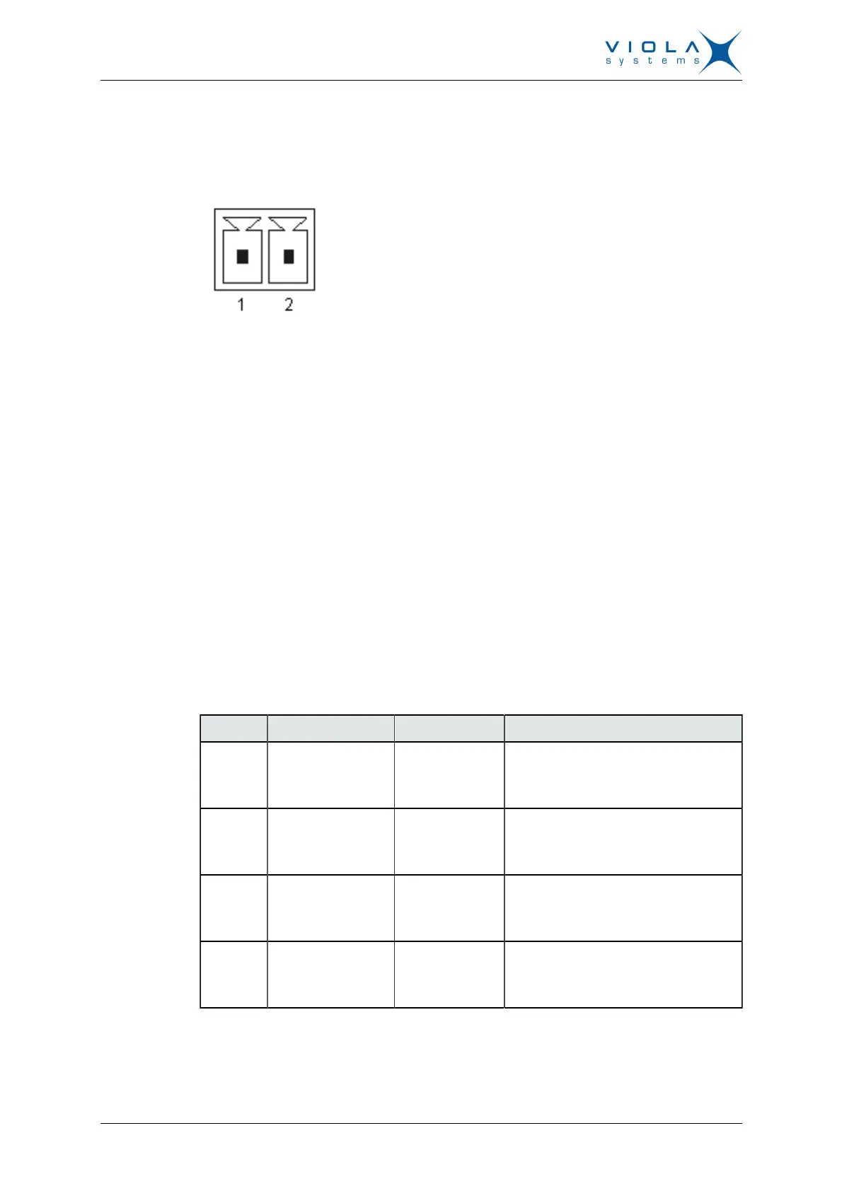
The Arctic has a 10 – 26 VDC power supply connector as shown in Figure 3.
Figure 3. Power supply connector
■
Pin 1 is positive (+)
■
Pin 2 is negative (–)
The unit is protected against reversed polarity.
Power Switch
Enables or disables the operation of the Arctic.
Console Enable Switch
Enables or disables console access. When it is disabled, both serial ports may
be used as an application serial port. When the switch is in the right position,
RS1 is in serial port mode and when in the left position, RS1 is in console
mode.
DIP Switches
It selects an application port (RS-2) mode and settings (RS-232 or RS-485).
By default all are set to “0” when the port is acting as an RS-232. DIP switches
2-4 apply only when RS-485 mode is selected by DIP switch 1.
Table 1: DIP Switches
Number Function State Explanation
1 RS-232/RS-485
“0” = RS-232
”1” = RS-485
Selects RS-port operation
2 HALF/FULL
“0” = full
“1” = half
Selects between half-duplex (2-wire)
and full-duplex (4-wire)
3 BIAS
“0” = OFF
“1” = ON
RS-485 biasing
4 TERMINATION
“0” = OFF
“1” = ON
RS-485 termination
Serial Ports (RS-232, RS-422/485 -connectors)
Arctic has two serial port connectors. These are 9-pin male connectors (DB9).
A null modem cable may be used to connect the Arctic to a serial device or