EasyManua.ls Logo

Viper Responder LE 5701 User Manual

Viper Responder LE 5701
90 pages
To Next Page IconTo Next Page
Page #1 background imageLoading...
Page #1 background image
Responder LE Model 5701
Security and Remote Start
Installation Guide
Note: This product is intended for installation by a professional installer
only! Any attempt to install this product by any person other than a trained
professional may result in severe damage to a vehicle’s electrical system and
components.
© 2008 Directed Electronics, Vista, CA
N5202V 2008-02
Question and Answer IconNeed help?

Do you have a question about the Viper Responder LE 5701 and is the answer not in the manual?

Viper Responder LE 5701 Specifications

General IconGeneral
BrandViper
ModelResponder LE 5701
CategoryRemote Starter
LanguageEnglish

Summary

Warning! Safety first

Installation points to remember

Deciding on component locations

Finding the wires you need

Obtaining constant 12V

Methods and important notes for locating and connecting the constant 12V power source.

12V switched ignition wire identification

Starter wire identification

Making your wiring connections

Primary and Auxiliary harness wiring

Door lock, Heavy gauge, and Remote start input harnesses

Wire connection guides

Auxiliary harness (H2) connections

Heavy Gauge, 10-pin connector wiring

Remote start input - 5-pin connector

Neutral safety switch interface

Testing the neutral safety switch

Procedure to test the neutral safety switch functionality for safe remote start operation.

Remote control learn routine

System features learn routine

Menu 3 - Remote start features

Menu 3 - Remote start options

Manual transmission remote start

Remote starting diagnostics

Remote start safety check

Essential tests to verify proper installation and safe operation of the remote start.
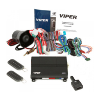
Troubleshooting

Remote start troubleshooting

Responder LE Quick Reference Wiring Guide

Related product manuals