2-4
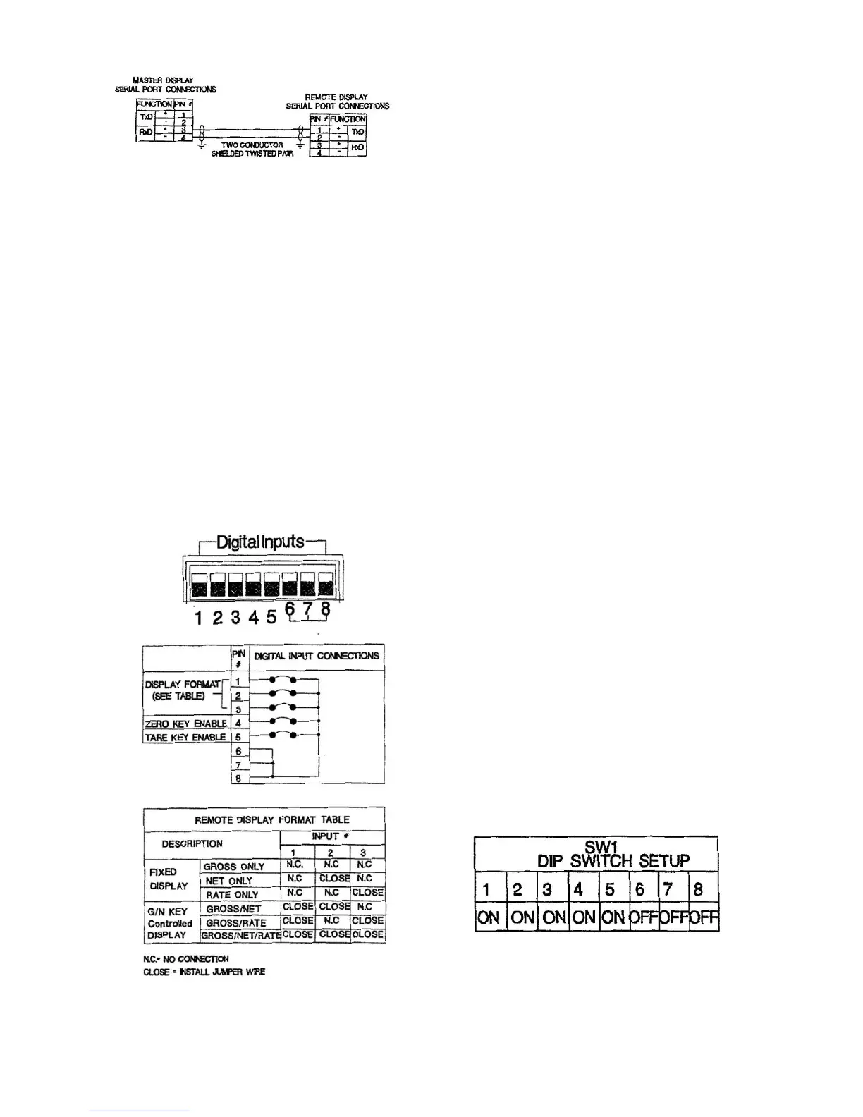
Figure 2-6. Serial Communication Wiring
Configuration
2.4 INTRODUCTION
Remote Digital Display is accomplished using
jumpers and DIP switch selections. Jumpers
determine the front panel display status and DIP
switch selection establish the communication
interface. Jumpers are added to the rear panel
Digital Input connector.
2.5 FRONT PANEL DISPLAY STATUS
Figure 3-1 gives a complete overview of jumper
status designations and locations. Designated
functions are discussed in the following
paragraphs.
Figure 3-1. Jumper Designations
2.5.1 DISPLAY MODE
The front panel display can be configured to
track the front panel of the host LCp/2020
instrument or fixed to display only one mode of
host operation. In tracking mode, any host mode
change (i.e. Net/Gross/ Rate) is immediately
transmitted and displayed upon the remote
display front panel. If a fixed display mode is se-
lected, the remote unit displays only the selected
mode of operation regardless of changes made
to the host device. For example, a remote LCp-
200R can be fixed to display rate data only while
the host LCp-200 freely changes from Gross to
Net or Rate.
2.5.2 DISPLAY CONTROL
When any tracking display is selected, pressing
the front panel GIN key changes not only the
remote but also the host mode of operation. The
remote display selection is transmitted back to
the host and the host mode of operation
changes accordingly. If the zero and tare keys
are activated (next paragraph), all net, gross,
rate, zero, and tare functions can be controlled
from the remote display keypad.
2.5.3 ZERO AND TARE FUNCTIONS
For remote control of system zero and tare
functions, add jumpers 4 and 5 as shown in
Figure 3-1. Jumpers may be added
independently as desired, i.e., zero only (4) or
tare only (5).
2.6 COMMUNICATION CONFIGURATION
To ensure proper bi-directional communication
between the remote display and the host, set
DIP Switch SW1 on both units as shown in
Figure 3-2.
Figure 3-2. DIP Switch Designations
*Rate not available with LCp-100 based systems
 Loading...