2-3
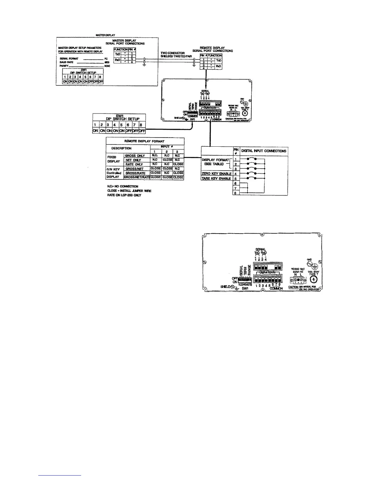
Figure 2-4. Interface Overview
2.3 ELECTRICAL CONNECTIONS
Figure 2-4 presents an overview of all wiring
connections. Use this interface diagram for
interface connections between the Remote
Display and host instrument. Individual
connections are discussed in the following
paragraphs.
2.3.1 THE REMOTE DISPLAY REAR PANEL
Figure 2-5 shows the Remote Display rear
panel. Call outs depict wiring locations for all
electrical connections.
2.3.2 MAINS (AC) POWER
Remote Display instruments are shipped ready
to operate at 115 Vac (50 or 60 Hz). For 220
Vac operation, remove the rear panel and
change the internal voltage selection switch by
performing the following:
1) Remove the mother board screws.
2) Slide the mother board out about 3 inches
3) Change the AC switch on the right-hand
side of the board
Figure 2-5. Rear Panel Connection Locations
Each instrument is protected with a 1/4 amp, 250
volt T type fuse located adjacent to the ac power
socket. If the fuse opens, replace it with the same
type, current, and voltage rating.
2.3.3 SERIAL COMMUNICATION
A 4-socket mating half connector is provided
for serial communication wiring. Connect
wires for both units as shown in Figure 2-6.
Total cable length should not exceed 200 feet.
 Loading...