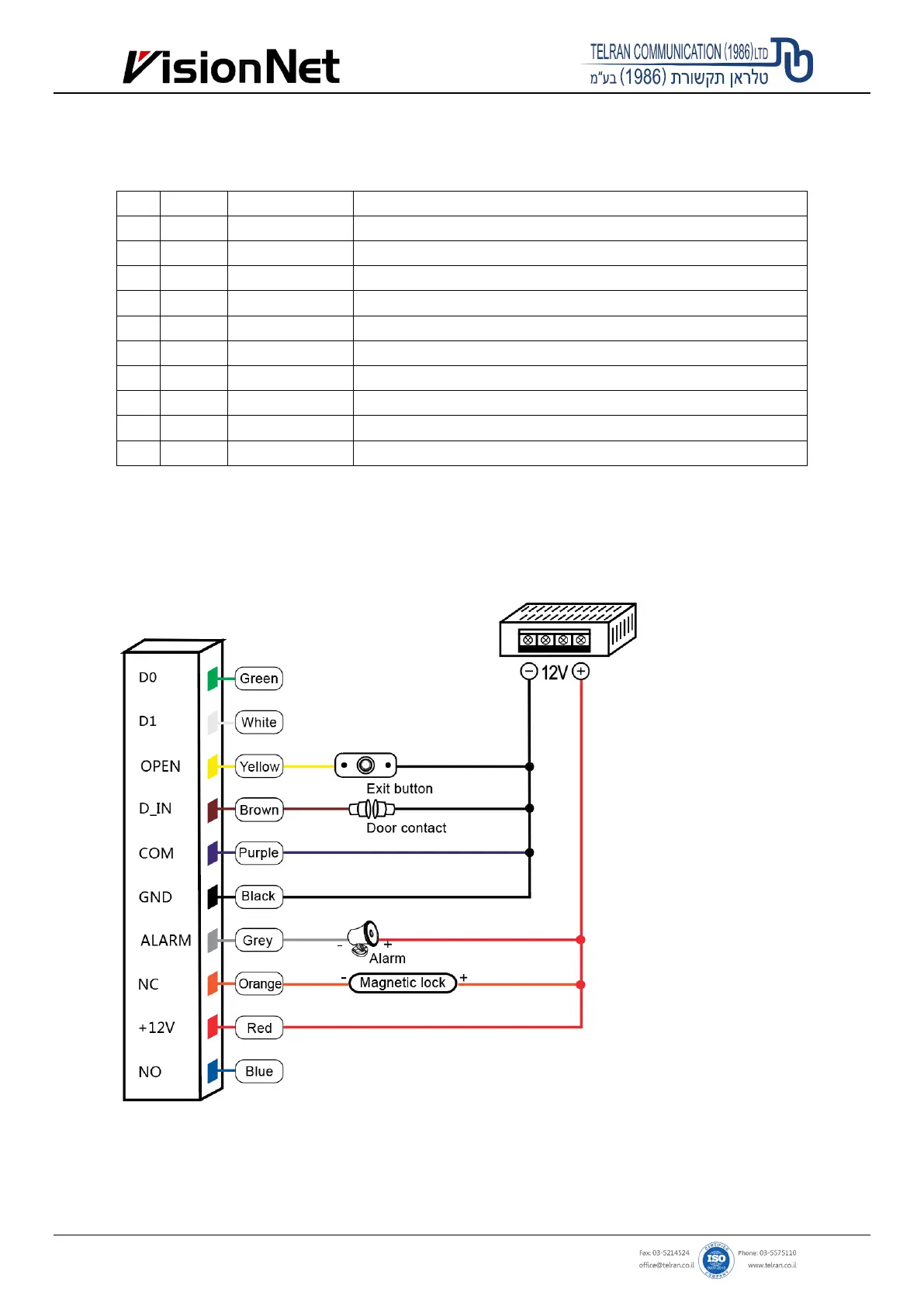
5. Wiring
No. Color Marks Description
1 Green D0 Wiegand input (Wiegand output as reader mode)
2 White D1 Wiegand input (Wiegand output as reader mode)
3 Grey ALARM Alarm signal MOS tube drain output end (optional)
4 Yellow OPEN/ BEEP Exit button input end (Beeper input as reader mode)
5 Brown D_IN/ LED Door contact switch input (LED input as reader mode) (optional)
6 Red +12V Positive power supply or AC power supply end
7 Black GND Negative power supply
8 Blue NO Relay NO end
9 Purple COM Relay COM end
10 Orange NC Relay NC end
6. Diagram
6.1 Common Power Supply
Note: The door contact and alarm function are optional