2 DE3637
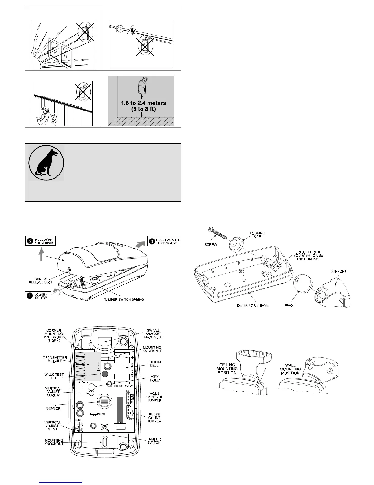
Prevent direct sunlight from
reaching the detector
Keep wiring away from
electrical power cables
Do not install behind partitions
The unit must be installed so that the expected motion of a
intruder would be perpendicular to the zones of detection.
Important! The detector is immune to 36 kg
(80 lb) animals moving on the floor or
climbing on furniture as long as the activity
takes place below 1 m (3 ft). Above the 1 m
(3 ft) height limit, the detector is immune to
18
kg
(40
lb)
pets,
but
the
pet
immunity
will
decrease as the pet gets closer to the detector. It is therefore
recommended to select a mounting location that minimizes
potential close proximity of animals.
3.2 Battery Insertion
It is recommended to power up the detector and let the target
receiver “learn” the transmitter’s ID before actual installation.
A . Remove the front cover as shown in Figure 2.
Figure 2. Cover Removal
B. Insert the battery into the battery clip - observe polarity (see
Figure 3).
Figure 3. Inside View
C . Press the tamper switch once and release it. This will perform
the reset necessary for smooth power up.
D . Put the cover on and watch the LED. It will flash once in 2
seconds for at least 15 seconds until the sensor stabilizes.
3.3 Enrolling the Transmitter ID into
the Target Receiver’s Memory
Refer to the target receiver’s installation instructions and follow the
procedure given there for “teaching” transmitter IDs. It is much
easier to carry out this operation in close proximity to the receiver.
3.4 Mounting without Swivel Bracket
A. Remove the front cover as shown in Figure 2.
B. Loosen the vertical adjustment screw, slide the PCB down
and remove it via the “keyhole” (see Figure 3).
C. Punch out the mounting knockouts at the rear wall of the base
(for surface mounting) or mounting knockouts at the angled
sides of the base (for corner mounting).
D. Hold the base against the wall at the selected installation
location and mark the points for drilling.
E. Drill the holes and insert the plastic anchors supplied (if
necessary).
F. Return the PCB to its place: align the ”keyhole” with the head
of the vertical adjustment screw, press the PCB against the
base, slide the PCB up and temporarily tighten the screw.
3.5 Mounting with Swivel Bracket
A. Remove the front cover as shown in Figure 2.
B. Loosen the vertical adjustment screw, slide the PCB down
and remove it via the “keyhole” (see Figure 3).
C. Punch out the large knockout in the round bulge at the top
part of the base (see Figure 4)
Figure 4. Attaching the Bracket
D . Assemble the bracket as shown in Figure 4.
E . Rotate the bracket to the desired position (see Figure 5) but
do not yet tighten the screw fully.
Figure 5. Wall and Ceiling Positions of Bracket
F . Hold the bracket against the mounting surface, mark the
points for drilling, drill out the holes and insert plastic anchors.
G . Attach the bracket to the mounting surface using the two
screws supplied.
H. Swivel the detector horizontally to face the desired direction,
but do not tilt it if this is a pet immune application. However, if
pets are not present it is advisable to tilt the detector as much
as 20° down. Figure 6 shows the tilt/swivel possibilities.
 Loading...