DE3637 3
Figure 6. Tilt/Swivel Limits
I. Having pointed the detector as desired, tighten the bracket
screw strongly, to prevent any further change of position.
Note: Improper use of bracket may reduce the forward range
and affect the dead zone areas.
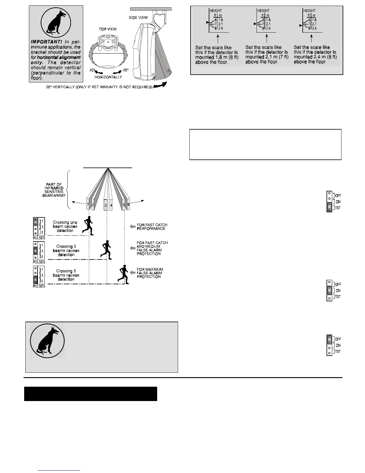
3.6 Setting the Pulse Counter
K-940MCW detectors are equipped with a programmable pulse
counter which can be set to count 1, 3 or 5 pulses, before
activating the wireless transmitter. Place the pulse count jumper
at the desired setting (1, 3 or 5 - see Figure 7).
Figure 7. Setting the Pulse Counter
3.7 Vertical Adjustment
A. Pet-Immune Applications
To maintain maximum coverage range and
pet immunity, the vertical adjustment scale
must be adjusted in accordance with the
actual mounting height (refer to Figure 8).
Loosen the vertical adjustment screw and
slide
the
printed
circuit
board
up
or
down
until
the pointer shows the actual mounting height on the scale.
When done, re-tighten the screw well.
Figure 8. Vertical Adjustment
B. Pet-Free Locations
To obtain the best coverage possible where no pets are present,
mount the detector with the integral bracket at any desired height
between 1.8 m (6 ft) and 2.4 m (8 ft). Then set the vertical
adjustment scale to the 2.4 m (8 ft) position and tilt the detector
20° down.
3.8 Walk Testing
IMPORTANT! The range and the coverage area of the unit
should be checked at least once a year. To assure proper
continuous functioning, the end user should be instructed to
perform a walk test at the far end of the coverage pattern prior
to each time the alarm system is armed.
To save battery power in normal use, an automatic timer inhibits
the detector for approximately 2 minutes after transmitter
activation. The detector is automatically rearmed 2 minutes after
detection of the last motion.
For effective walk testing , it is necessary to override the
2 minute timer by setting the LED/WALK-TEST jumper to
the TEST position as shown to the right.
➜
Remember that in this mode, the supervision test
message will be transmitted at 1 minute intervals instead
of 1 hour intervals.
IMPORTANT! Once the cover is replaced, the detector goes
through a stabilization period. The LED will flash once per 2
seconds until the detector has stabilized (stabilization time
is at least 15 seconds).
A. Walk-test the entire protected area by walking slowly across
the detector's field of view, observing the LED. Pause for 5
seconds after each test to allow the unit to complete its
3-transmission sequence (see Appendix A); the LED will light
for 2 seconds.
B. Set the LED/WALK-TEST jumper to the ON position
as shown to the right.
➜
Wait outside the coverage area. After five minutes,
re-enter the coverage area and verify that the LED
lights for 2 seconds upon detection.
C. If you continue moving, the unit will remain disabled due to the
2-minute battery saving timer. The unit will be rearmed
provided that no motion is detected for approximately 2
minutes, and will then be ready to detect and transmit.
D. When done, set the LED/WALK-TEST jumper to the
OFF position as shown to the right.
➜
This setting is recommended to prevent unauthorized
people from tracing the detector’s coverage pattern.
4
44
4. NOTES AND WARNINGS
. NOTES AND WARNINGS. NOTES AND WARNINGS
. NOTES AND WARNINGS
4.1 Product Limitations
Visonic Ltd. wireless systems are reliable and are tested to high
standards. However, due to the low transmitting power (required
by the FCC and other regulatory authorities), there are some
limitations to be considered:
A . A receiver may be blocked by radio signals sent on or near its
operating frequency, regardless of the digital code used.
B . A receiver responds to one transmitted signal at a time.
C . Wireless equipment should be tested regularly (at least once
a week) to discover sources of interference and to protect
against faults.
4.2 Compliance with Standards
This device complies with FCC Rules Part 15. Operation is
subject to two conditions: (1) This device may not cause harmful
interference, and (2) this device must accept any interference that
may be received or that may cause undesired operation.
 Loading...