DE5110 15
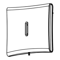
Figure 5.3 Using a
Screwdriver to Open the Case
Figure 5.4 Keypad Base
Layout
&RQQHFWLQJ WKH .H\SDG WR WKH %XV
Although there is a difference in component layout between the
KP-1001 and KP-1002/KP-1003, all types of keypad accommodate
the same terminal block at the same location on the printed circuit
board. For this reason, only the KP-1001 printed circuit board is
shown (Fig. 5.5). The terminals are numbered from 1 to 4. If you
are using a color coded bus cable, note down the color of the wire
connected to each one of the control module's BUS terminals.
Going by colors, make a "one for one" connection, where terminal
1 in the control module is connected to terminal 1 in the keypad,
terminal 2 to terminal 2, etc.
Figure 5.5 Connecting a Keypad to the Keypad Bus
IMPORTANT! If the keypad bus is cut off and not even a single
keypad is left connected to the alarm control module, a silent
alarm will be initiated, meaning that the communicator will send a
"keypad bus error" event code to the central station.
Keypad bus error will be reported provided that you program the
required event code in Location 34 - refer to the Installer's
Programming Manual.
Upon reconnection of the keypad, a "keypad restore" message
will be sent to the central station (provided that you program the
required event code in Location 34).
(;3=21((;3$1'(5237,21
'HVFULSWLRQ DQG 8VH
The zone expander is a micro-processor controlled module
designed to increase the system zone capacity from 8 to 16. It can
be mounted either within the metal cabinet that hosts the alarm
control module, or separately elsewhere within the protected area.
If located within the metal cabinet, the EXP-1600 is connected to
the control module via a short flat cable terminated with 4-pin
plugs (this cable is supplied with each expander). Special 4-pin
sockets are provided for this purpose on both the expander board
(Fig. 6.1) and the control module board.
Installation away from the system control housing reduces the
distance between the expander and its associated zone detectors.
 Loading...