16 DE5110
A remotely located zone expander is connected to the control
module via the same 4-wire bus that serves the control keypads.
The bus, that utilizes multiplex communication techniques, is being
constantly supervised by the control module, and a trouble alert is
generated if a malfunction occurs. The EXP-1600 accommodates
terminals for the additional 8 zones, and 12 VDC output terminals
for supplying power to detectors used in the additional 8 zones.
The 12VDC output terminals are especially useful in installations
where the detectors of the additional 8 zones are closer to the
expander than to the alarm control module. An optional plastic
housing - the UPB-3 - can be used for remote installation of the
EXP-1600 (Para. 6.2 B).
0RXQWLQJ
Any MAESTRO-1600 or MAESTRO-1600DL may be expanded to
control 16-zones by addition of the optional EXP-1600 module.
This module can be mounted within the control cabinet or at a
remote location, as described in the following paragraphs.
A. Mounting within the Alarm Control Cabinet
If you prefer to install the EXP-1600 within the metal cabinet, refer
to Fig. 1.1 for correct
location of this module.
Align the 4 mounting
holes of the expander
module with the 4 stand-
offs on the rear wall of
the metal cabinet. Use
four screws to fasten the
EXP-1600 to these 4
standoffs. Next, connect
the short flat cable
assembly supplied with
the EXP-1600 between
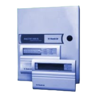
Figure 6.1 Zone Expander EXP-1600
the 4-pin sockets on the EXP-1600 and the alarm control module.
Align the plugs properly before insertion!
B. Distant Mounting
(Fig. 6.2 & 6.3)
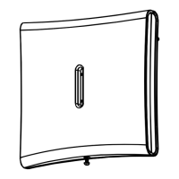
To mount the EXP-1600 in an optional UPB-3 housing:
(1)
Remove the screw that secures the UPB-3 cover to the base.
(2)
Insert a small screwdriver blade into the slot near one of the
snap-in teeth, as shown. Carefully flex the cover edge out, until
the tooth disengages the dent. Repeat this with the other tooth
to free the cover edge completely.
(3)
Lift the free edge of the cover diagonally up and get the other
edge free by pulling it backwards to disengage tabs at back.
( 4 )
Hold the base against the mounting surface and mark the
points for drilling.
( 5 )
Drill the mounting holes and insert wall anchors if necessary.
Insert the wires into the base via any of the wiring holes.
Attach the base to the mounting surface with two screws.
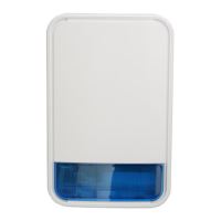
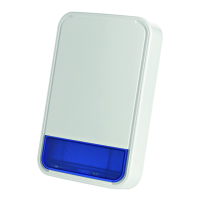
( 6 )
Put the expander
module in place (see
Fig. 6.3) with the bottom
edge seated in the
module edge support.
Align the holes at the top
of the PCB with the
plastic standoffs in the
base. Secure the mo-
dule to the base with
short hold-down screws
( 7 )
If you wish to protect the
UMB-3 housing with a
tamper switch, obtain a
self-adhesive magnetic
switch. Attach the
magnet to the cover and
the switch to the base
Wire the switch to a
zone programmed for 24
- hour tamper operation.
Figure 6.2 UPB-3,Cover Removal
Figure 6.3 UPB-3 Base with
EXP-1600
 Loading...