DE5110 5
7+($/$50&21752/&$%,1(7
$ODUP &RQWURO 0RGXOH 'HVFULSWLRQ
As the nerve center or the brain of the entire alarm system, this
programmable module includes the hardware and firmware
necessary for managing the system with or without auxiliary
modules - the communicator, zone expander and the siren driver.
It must be stressed, though, that at least one keypad/display unit is
required to set up a workable 8-zone alarm system.
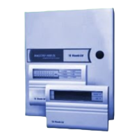
Figure 3.1 The MAESTRO-1600 Control Module
The control module (Fig. 3.1) comes mounted within the alarm
control cabinet. Its printed circuit board is equipped with a socket
for the communicator module (at the left hand edge) and a socket
for the siren driver module (at the right hand edge).
Operating power is supplied from a 16 VAC / 40 VA stepdown
transformer - part of the power pack kit PK-1. The control module
accommodates a voltage regulator and a charger for the backup
battery. Regulated 12 VDC output for the detectors, all the
keypads and other external devices is obtained via an on-board 1A
fuse marked "ACCESSORIES". Two pairs of 12VDC output
terminals are provided, to allow easier connection of a large
number of accessories.
The ALARM relay has changeover (Form 1C) dry contacts rated at
5A/24 Volts, and can be used to activate alarm devices such as
sirens or bells (Fig. 3.7). A jumper marked V-BELL connects the
12 VDC supply to the common (C) contact of the alarm relay, via a
3A fuse marked BELL. With the jumper installed across the two
V-BELL pins, the bell or siren can be wired between the N.O.
contact of the relay and the negative (–) supply terminal.
3RZHU 3DFN .LW 3.
The AC power pack for the MAESTRO-1600 is delivered
separately in kit form, to suit the mains voltage and the particular
regulations in the country of use. The kit includes a step-down
transformer, an AC mains terminal block with a built-in fuse holder
and a 0.3 A fuse, mounting hardware and a terminal identification
sticker. As an essential part of the alarm control system, the power
pack must be installed in the metal cabinet (Fig 3.2) and wired
accordingly (Fig. 3.3).
A. Align the transformer mounting ears with the 2 stand-off screws
on the rear wall of the case and let the screws pass through the
holes. Mount a flat washer, a lock washer and a nut (in this
order) on each screw and tighten both nuts.
B . Place AC mains terminal block with its ground lug over the
stand-off grounding screw, and the hole nearest to the fuse
holder over press nut. Pass a screw (supplied in the kit)
through that hole and thread it into press nut. Tighten screw
well. Put a lock washer and a nut over the stand-off grounding
screw and tighten nut to fasten ground lug to the case.
C. Remove the paper backing from the terminal identification
sticker and attach the sticker to the rear wall of the case, as
close as possible to the AC terminal block.
 Loading...

