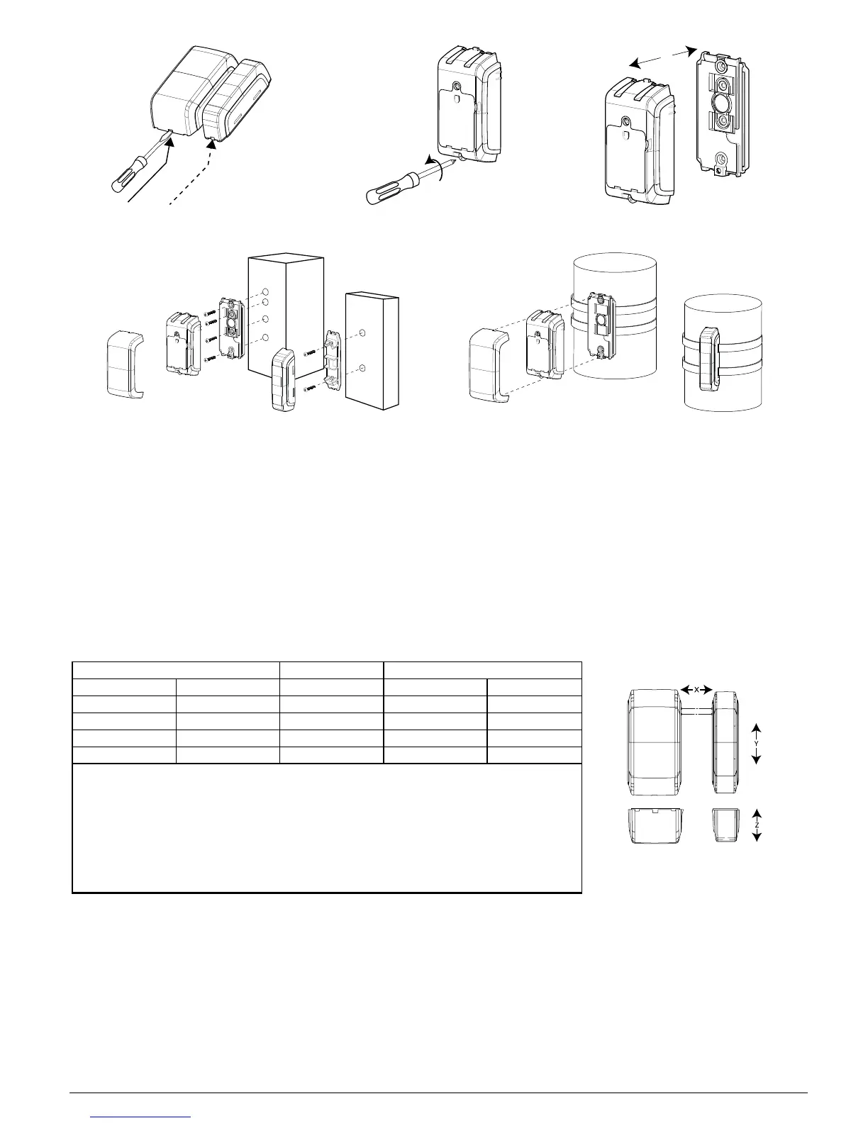
Figure 2 - Decorative cover removal Figure 3 - Unscrewing device Figure 4 - Device and bracket separation
Figure 5 - Flat surface mounting Figure 6 - Curved surface mounting
2.2. Mounting the MC-312 PG2 on a curved surface
1. Insert a flat-head screwdriver into the slot provided and push upward to remove the decorative cover, as in Fig. 2.
2. Unscrew the lower screw from the device cover, as in Fig. 3.
3. Separate the device from the bracket, as in Fig. 4.
4. Feed both straps through the slots provided in the bracket, as in Fig. 6.
5. Fasten both straps to the desired curved surface and position the connecting sections of the straps at the location of the bracket.
6. Separate the magnet bracket and cover and feed both straps through the slots provided on the cover.
7. Close the magnet and fasten both straps to the desired curved surface and position the connecting sections of the straps at the location of the
bracket.
Note: Align the device and magnet according to the specifications in "Range coverage directions" below.
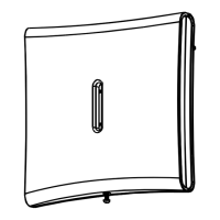
2.3. Range coverage directions
Non-metallic surface Supports Metallic surface
Open Close Direction Open Close
71 mm 52 mm X 48 mm 35 mm
40 mm 33 mm Y (up) 32 mm 25 mm
22 mm 17 mm Y (down) 17 mm 8 mm
85 mm 55 mm Z 55 mm 30 mm
Table 1 - Range coverage directions
Note: Values stated above may vary by up to 10%. For steel installations, the gaps cannot be less than
3.2 mm.
Note: In case of roller shutter assembly, the magnet needs to be mounted 25 mm - 35 mm (on the X
plane) from the device. For all other installations, a minimum gap of 5 mm is needed.
Tip: When mounting on a slide door, refer to X. When mounting on a roller shutter, refer to Y. When
mounting on a normal door, refer to Z.
Figure 7 - Range coverage directions
D-307174 MC-312 PG2 Installation Instructions 2