2 DE1274
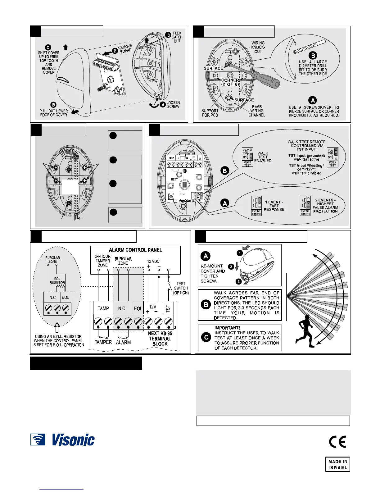
3.2 Illustrated Installation Procedure
WIRES
RECOM-
MENDED
CORNER
MOUNT
SURFACE
MOUNT
(1 OF 2)
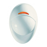
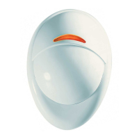
1.8-2.4m (6-8ft) above ground. For range above
10m (30ft) recommended height is up to 2.1m (7ft)
SINGLE-
SIDE, 45°
ANGLED
MOUNT
SINGLE-
SIDE, 45°
ANGLED
MOUNT
ROUTE
WIRES INTO
B
INSERT
DOWELS
C
PUT P.C.
BOARD
D
MARK
DRILLING
A
BASE VIA THE
REAR CHANNEL
& ATTACH BASE
TO WALL WITH
TWO SCREWS
BACK IN PLACE
POINTS AND
DRILL IN WALL
4
44
4. SPECIAL COMMENTS
. SPECIAL COMMENTS. SPECIAL COMMENTS
. SPECIAL COMMENTS
Even the most sophisticated detectors can sometimes be defeated or may fail to
warn due to: DC power failure / improper connection, malicious masking of the
lens, tampering with the optical system, decreased sensitivity in ambient
temperatures close to that of the human body and unexpected failure of a
component part.
The above list includes the most common reasons for failure to detect intrusion,
but is by no means comprehensive. It is therefore recommended that the
detector and the entire alarm system be checked weekly, to ensure proper
performance.
An alarm system should not be regarded as a substitute for insurance. Home
and property owners or renters should be prudent enough to continue insuring
their lives and property, even though they are protected
by an alarm system.
This device has been tested and found to comply with the limits for a Class B digital device, pursuant
to Part 15 of the FCC Rules. These limits are designed to provide reasonable protection against
harmful interference in residential installations. This equipment generates, uses and can radiate radio
frequency energy and, if not installed and used in accordance with the instructions, may cause
harmful interference to radio and television reception. However, there is no guarantee that
interference will not occur in a particular installation. If this device does cause such interference,
which can be verified by turning the device off and on, the user is encouraged to eliminate the
interference by one or more of the following measures:
– Re-orient or re-locate the receiving antenna.
– Increase the distance between the device and the receiver.
– Connect the device to an outlet on a circuit different from the one that supplies power to the receiver.
– Consult the dealer or an experienced radio/TV technician.
WARNING! Changes or modifications to this unit not expressly approved by the party
responsible for compliance could void the user’s authority to operate the equipment.
VISONIC LTD. (ISRAEL): P.O.B 22020 TEL-AVIV 61220 ISRAEL. PHONE: (972-3) 645-6789, FAX: (972-3) 645-6788
VISONIC INC. (U.S.A.): 10 NORTHWOOD DRIVE, BLOOMFIELD CT. 06002-1911. PHONE: (860) 243-0833, (800) 223-0020 FAX: (860) 242-8094
VISONIC LTD. (UK): FRASER ROAD, PRIORY BUSINESS PARK, BEDFORD MK44 3WH. PHONE: (0870) 730-0800 FAX: (0870) 730-0801
INTERNET:
www.visonic.com
VISONIC LTD. 2002 NEXT K9-85 DE1274- (REV. 3, 10/02) Refer to a separate warranty statement
1 2
4
3
65
Set
 Loading...