4 D-305903 NEXT PLUS Installation Instructions / Instrucciones de instalación / Instruções de instalação
5 10 15 m
0
2.1 m
(6.9 ft)
16.4 32.8 49.2 ft
90°
5
0
16.4
0
15 m
49.2 ft
10
32.8
5m
16.4ft
5m
16.4ft
10m
32.8ft
10m
32.8ft
GB/US: HORIZONTAL VIEW
SP: VISTA HORIZONTAL
PT:VISTA HORIZONTAL
GB/US: VERTICAL VIEW
SP: VISTA VERTICAL
PT: .VISTA VERTICAL
GB/US:
DUO, DUO K9-
85, DUO AM & DUO AM
K9-85 only
SP:
Sólo DUO, DUO K9-
85, DUO AM y DUO AM
K9-85
PT:
Só DUO, DUO K9-85,
DUO AM e DUO AM K9-
85
PIR, DUO, DUO AM: 0.5-4m
K9-85, DUO K9-85, DUO AM
K9-85: 2-4m,
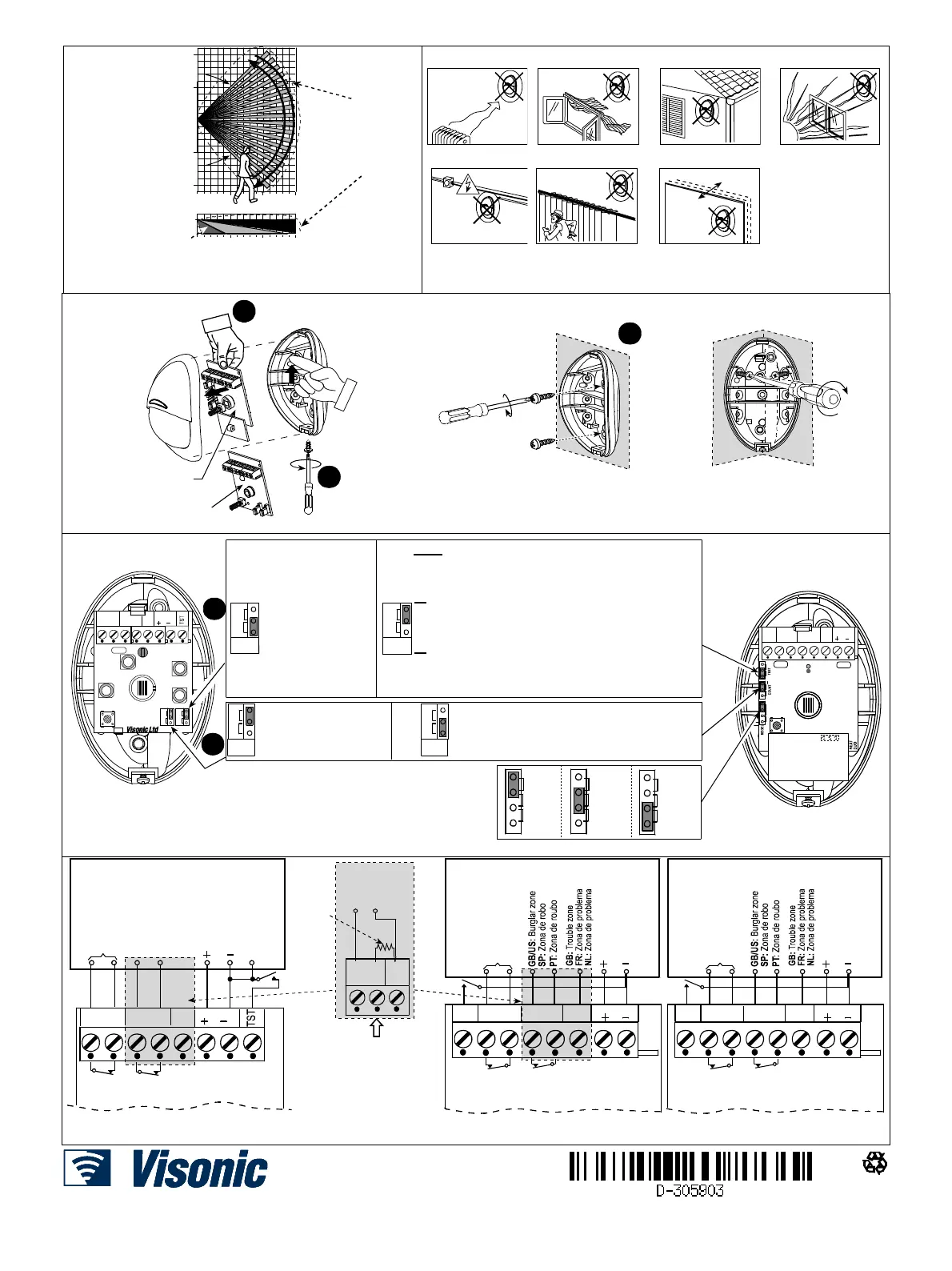
Fig. 2 - Coverage pattern walk-test / Prueba de detección del
te de detecção da área de cobertura
1
2
3
4
5 6
7
Fig. 3 - General guidelines / Consejos generales / Conselhos gerais
PIR & K9-85
2
1
3
GB/US: In corner
SP: En esquina
PT: Na esquina
GB/US: Mounting
SP: Montaje
PT: Montagem
GB/US: On surface
SP: En superficie
PT: Na superficie
GB/US: Release screw
and remove cover
SP: Quite el tornillo y la
tapa
PT: Desaperte o parafuso
e retire a tampa
GB/US: Push catch and remove board
SP: Empuje la pestaña de fijación y quite la placa
PT: Empurre a patilha e retira a placa
DUO, DUO K9-85,
DUO AM & DUO AM
K9-85
Fig. 4 - Mounting / Montaje/ Montagem
N.C EOL
12V
TAMP
EVENT
COUNT
WALK
TEST
VIA
TST
ON
2
1
1
2
K9-85
DUO, DUO K9-85,
DUO AM,
DUO AM K9-85
5
15
10
5
15
10
5
15
10
15 m
(49 ft)
10 m
(32 ft)
5 m
(16 ft)
GB/US: Range selection
SP: Selección de cobertura
PT: Selecção de escala
WALK
TEST
ON
VIA
TST
GB/US: Walk test enabled
GB/US
Walk test remote controlled via TST input:
TST Input grounded: walk test active
TST Input “floating” or “+12V”: walk test disabled
WALK
TEST
ON
VIA
TST
SP: Prueba de detección
activada.
PT: Teste de passagem
activo
SP
Prueba de detecciòn remota controlada por la entrada TST
Entrada TST conectada a negativo: Prueba de detección activada.
Entrada TST “flotante” o “+12V”: prueba de detección desactivada
PT
Teste de passagem remoto controlado pela entrada TST:
Entrada TST ligada ao negativo (0V): Teste de passagem activo
Entrada TST “no ar” ou ligada a “+12V”: teste de passagem desactivo
EVENT
COUNT
2
1
GB/US: 1 event - fast response
SP: 1 evento - respuesta rápida
PT: 1 evento - resposta rápida
GB/US: 2 events - Highest false alarm protection
SP: 2 eventos - La mayor protección contra falsas alarmas
PT: 2 eventos - Maior protecção contra falsos alarmes
EVENT
COUNT
2
1
TEST TAMP N.C EOL
12V
VIA
ON
5
1
2
15
10
Fig. 5 - Jumpers setting / Colocación de los jumper / Configuração dos jumpers
GB/US: Test switch (option) SP: Interrruptor de prueba (opcional) PT:
Interruptor de teste (opcional)
(*)
TEST N.C
TAMP
GB/US: ALARM CONTROL PANEL
SP: CENTRAL DE ALARMA
PT: PAINEL DE CONTROLE DO ALARME
GB/US: 24h
tamper zone
SP: Zona de
tamper 24 h
PT: Zona de
tamper 24 h
12V
12 VDC /
12 VCC /
12VCC
EOL
DUO &
DUO K9-85
(*)
Alarm /
Alarma /
Alarme
Tamper /
Tamper /
Tamper
12 VDC /
12 VCC /
12VCC
N.C
EOL
12V
TAMP
Alarm /
Alarma /
Alarme
Tamper /
Tamper /
Tamper
GB/US: Burglar zone
SP: Zona de robo
PT: Zona de roubo
PIR &
K9-85
GB/US: 24h
tamper zone
SP: Zona de
tamper 24 h
PT: Zona de
tamper 24 h
GB/US: ALARM CONTROL PANEL
SP: CENTRAL DE ALARMA
PT: PAINEL DE CONTROLE DO ALARME
(*)
GB/US: using an E.O.L. resistor when
control panel is set for E.O.L. operation
SP: Utilizando una R.F.L. cuando la central
está configurada para funcionar con R.F.L.
PT: Utilize uma R.F.L. quando a central está
configurada para isso
N.C
EOL
GB/US: EOL
resistor
SP: R.F.L
PT: R.F.L
GB/US: Burglar
zone
SP: Zona de robo
PT: Zona de roubo
TEST N.C
TAMP
GB/US: ALARM CONTROL PANEL
SP: CENTRAL DE ALARMA
PT: PAINEL DE CONTROLE DO ALARME
GB/US: 24h
tamper zone
SP: Zona de
tamper 24 h
PT: Zona de
tamper 24 h
12V
12 VDC /
12 VCC /
12VCC
TRB
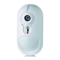
DUO AM &
DUO AM K9-85
(*)
Alarm /
Alarma /
Alarme
Tamper /
Tamper /
Tamper
Fig. 6 - Wiring / Cableado de la regleta de conexiones / Ligações
EMAIL: info@visonic.com
INTERNET: www.visonic.com
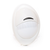
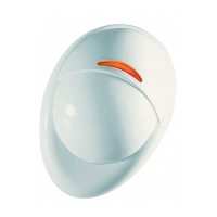
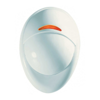
NEXT PLUS SERIES, PIR, K9
 Loading...