DE1029 1
NEXT PIR
NEXT PIRNEXT PIR
NEXT PIR
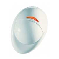
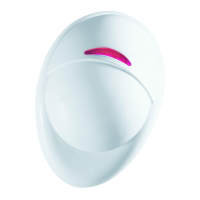
Digital PIR Detector with TMR™ Signal Processing
Installation Instructions
1
11
1. INTRODUCTION
. INTRODUCTION. INTRODUCTION
. INTRODUCTION
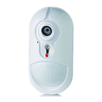
The NEXT PIR is a microprocessor-controlled PIR detector,
designed for easy installation, free of vertical adjustment. It features
a cylindrical lens with uniform detection sensitivity beginning at 0.5
meter away from the detector up to a distance of 12 meters (40 ft).
The advanced True Motion Recognition™ algorithm (patented)
allows the NEXT PIR to distinguish between the true motion of an
intruder and any other disturbances which cause false alarms.
A TST (Test) input permits switching the detector to the walk test
mode remotely without removing the front cover. An on-board
motion event jumper determines whether 1 or 2 consecutive
motion events would trigger an alarm.
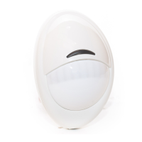
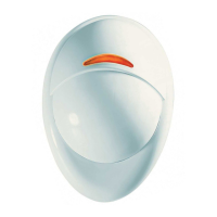
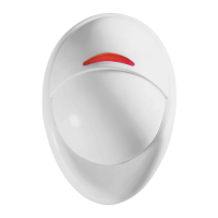
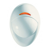
Figure 1. General View
Figure 2. Inside View
2
22
2. SPECIFICATIONS
. SPECIFICATIONS. SPECIFICATIONS
. SPECIFICATIONS
Input Voltage: 9 to 16 VDC
Current Drain: About 8 mA @
12 VDC
OPTICAL (see Figure 3)
Lens Data
No. of curtain beams: 9 + 5
Max. Coverage: 12 x 12 m
(40 x 40 ft) / 90°
ALARM and TAMPER
Alarm Output: Solid-state relay,
N.C., up to 100 mA / 30 V, ~30 Ω
internal resistance. Circuit opens
for 2-3 seconds upon alarm.
Alarm Indication: LED lights
for 2-3 seconds.
Figure 3. Coverage Pattern
Event Counter: Selectable, 1 or 2 motion events
Tamper Contacts: Normally closed, 50 mA resistive / 30 VDC
MOUNTING
Surface or corner, at the height of 1.8 to 2.4 m (6 to 8 ft)
Note: Base allows single-sided corner mount at 45° to wall.
ACCESSORIES:
BR-1: Surface mounted swivel bracket, adjustable 30° down and
45° left/45° right.
BR-2: BR-1 with a corner adapter
BR-3: BR-1 with a ceiling adapter
ENVIRONMENTAL
Operating Temperature: –10°C to 50°C (14°F to 122°F)
Storage Temperature: –20°C to 60°C (–4°F to 140°F)
RFI Protection: Greater than 20 V/m (20 MHz to 1000 MHz)
PHYSICAL
Size
(H x W x D): 94.5 x 63.5 x 49.0
mm
(3-11/16
x 2-1/2
x
1-15/16”)
Weight: Approximately 50 g (1-3/4 oz)
PATENTS: U.S. Patents 5,693,943 ! 6,211,522 ! D445,709
(another patent pending)
3
33
3. INSTALLATION
. INSTALLATION. INSTALLATION
. INSTALLATION
3.1 General Guidelines
3.2 Illustrated Installation Procedure
1 2
O