D-303359 MCT-320 SMA Installation Instructions 1
MCT-320 SMA
Wireless Contact Sensor
Installation Instructions
1. INTRODUCTION
The MCT-320 is a fully supervised, wireless magnetic contact sensor,
for use with iControl control panels. The sensor includes a built-in
reed switch (that opens upon removal of a magnet placed near it).
The MCT-320 tamper switch is activated when the cover is removed or
when the detector is removed from the wall.
A periodic supervision message is transmitted automatically. The target
receiver is thus informed, at regular intervals, of the unit’s active participation
in the system.
Operating power is obtained from an on-board 3 V Lithium battery. When
the battery voltage is low, a “low battery” message is sent to the receiver.
MCT-320 SMA
2. SPECIFICATIONS
WIRELESS
Frequency: Frequency: 2.4 GHz as per IEEE 802.15.4
Tamper Alert: Reported when a tamper event occurs and in any
subsequent message, until the tamper switch is restored.
Supervision Message: Signaling at 24-minute intervals.
ELECTRICAL
Internal Battery: 3V Lithium battery, type CR2. Use Panasonic, GP or
Sanyo only.
Battery Life Expectancy: 3-5 years (for typical use).
Battery Power Test: Performed immediately upon battery insertion and
periodically every several hours.
Battery Supervision: Automatic transmission of battery condition data as
part of any status report.
ENVIRONMENTAL
Operating Temperature: -10C to 55C (14F to 131F).
Dimensions: 51 x 30 x 21 mm (2 x 1-3/16 x 13/16 in.)
Weight (including battery): 36g (1.27 oz)
COMPLIANCE WITH STANDARDS
Designed to comply with UL 639, ULC-S306, Title 47 CFR Part 15, IC
RSS-210
This device complies with Part 15 of the FCC Rules and RSS-210 of Industry
and Science Canada. Operation is subject to the following two conditions: (1)
This device may not cause harmful interference, and (2) this device must
accept any interference received, including interference that may cause
undesired operation.
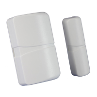
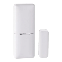
Fixed
frame
Moving
part
Transmitter & magnet
location marks
Fig. 1 – MCT-320 SMA
3. PAIRING/DEFAULTING THE SENSOR
To pair the sensor to the control panel, you must set it to pairing mode.
1. Press and hold down the sensor’s tamper switch.
2. Insert the battery into the sensor.
3. Release the tamper switch and press it again within 4 seconds.
4. Complete the pairing procedure on the control panel (see the pairing
instructions in the control panel’s installation guide).