D-302182 PGM-5 Installation Instructions 1
PGM
PGMPGM
PGM-
--
-5
55
5
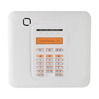
PowerMax Pro / PowerMaxComplete / PowerMaxExpress /
PowerMaster-10 G2 / PowerMaster-30 G2 /
PowerMaster-33 G2 Interface Unit
Installation
Instructions
1. DESCRIPTION
1. DESCRIPTION1. DESCRIPTION
1. DESCRIPTION
PGM-5 (see Figure 1) is an output interface module designed to
provide alarm, trouble events and status signals to external devices
such as long range wireless monitoring transmitters, CCTV systems,
home-automation systems, LED annunciation panels, etc.
The PGM-5 provides 5 solid state relay contact outputs and is designed
to be used as a plug-in internal add-on module with PowerMax Pro,
PowerMaxComplete, PowerMaxExpress, PowerMaster-10 G2,
PowerMaster-30 G2 and PowerMaster-33 G2 control panels.
Note: The PGM-5 will be active only if the PGM-5 option was enabled
in the factory default of the control panel. For PowerMaster control
panels v18 and above, it is required to enable or disable the PGM-5
via the Installer Mode. For detailed instructions, refer to the
PowerMaster Installer Guide.
Figure 1 – PGM-5 Printed Circuit
Outputs 1 to 4 provide pre-set signals while output 5 is programmable
using DIP switches SW-3 & SW-4 – see Tables 1 & 2.
Table 1 – Output Definitions
Output Event Type
OUT 1 Burglar & 24Hr audible alarm (Bell time duration).
Tamper & 24 Hr silent (2 sec. pulse)
OUT 2 Panic (2 sec. pulse)
OUT 3 Fire (Bell time duration).
OUT 4 Arm / Disarm (actual status of the panel)
OUT 5 See table 2
Table 2 – OUT 5 Signal Setting
SW-4 SW-3 Event Type
OFF OFF General trouble (until restored)
ON OFF General Low battery (until restored)
OFF ON Gas or CO alarm (until restored)
ON ON AC failure reported (until restored)
The outputs can be set to either normally open (N.O) or normally
closed (N.C), according to the specific application, using DIP switches
SW-1 (for outputs 1, 2, 3 & 5) and SW-2 for output 4 (Arm/Disarm) –
see table 3.
Table 3 – N.O or N.C Outputs Normal State Setting
OUT
1,2, 3 & 5
SW-1
OUT 4 SW-2
Each output will change its state upon occurrence of an event or change
of status and will revert to its normal state upon restoral of the event or
change of status.
Alarm types:
1. Alarm
2. Panic
3. Fire
4. Arm/disarm
5. Low bat./Gas Co/
AC fail./Gen. trbl
PowerMax Pro
PGM-5
Figure 2 – Typical Application
Figure 3 displays electrical wiring diagrams where the PGM-5 module
is connected to an alarm transmitter and to a LED Annunciation
Panel.
ALARM TRANSMITTER
INPUT 1
INPUT 2
INPUT 3
INPUT 4
INPUT 5
COM
or
( )
PGM-5
OUT 1
OUT 2
OUT 3
OUT 4
OUT 5
COM
PGM-5
OUT 1
OUT 2
OUT 3
OUT 4
OUT 5
COM
LED ANNUNCIATION
PANEL
12V
Alarm
Panic
Fire
Arm /Disarm
Programmable
0 V
LED
1 k
Ω
1 k
Ω
1 k
Ω
1 k
Ω
1 k
Ω
Figure 3 – Electrical Wiring of PGM-5 Module and Alarm
Transmitter/ LED Annunciation Panel