READING ALARM MEMORY AND TROUBLE DATA
DE5467U 17
• GSM line fail - GSM telephone line failure.
• GSM net fail - GSM network failure.
• RSSI low - The GSM received signal strength is
low.
• GSM modem off - The GSM unit does not
operate.
• GSM communication fail - There is no
communication (RS-232 format) between
PowerMax+ and GSM unit.
SYSTEM TROUBLES
• AC Supply Failure - There is no power and the
system is working on backup battery power (this
trouble is reported 5 minutes after its
occurrence).
• System Jammed - A radio-frequency signal is
blocking communication channel of sensors and
control panel.
• Communication failure - A message could not
be sent to the central monitoring station or to a
private telephone (or a message was sent but
was not acknowledged).
• CPU low battery - The backup battery within
the control panel is weak and must be replaced
(see Chapter 9 - Replacing Backup Battery).
• CPU tamper - The control panel is being
tampered with.
• Fuse Trouble - The siren fuse is burnt out.
IMPORTANT! If the trouble beeps bother you,
disarm the system again (even though it is already
disarmed). This will cancel the trouble beeps for 4
hours.
B. Investigating Trouble Sources
In a state of trouble, a flashing TRBL message is
displayed as shown in the following examples:
READY HH:MM
(alternating)
READY TRBL
or, if the system is not ready for arming -
NOT READY HH:MM
(alternating)
NOT READY TRBL
You can review the current troubles one by one, by
clicking the SHOW/OK button.
EXAMPLE:
The kitchen sensor - zone No. 9 - has
been inactive and the living room sensor - zone No.
15 - has reported a low battery. However, these
troubles do not prevent the system from being “ready
to arm”
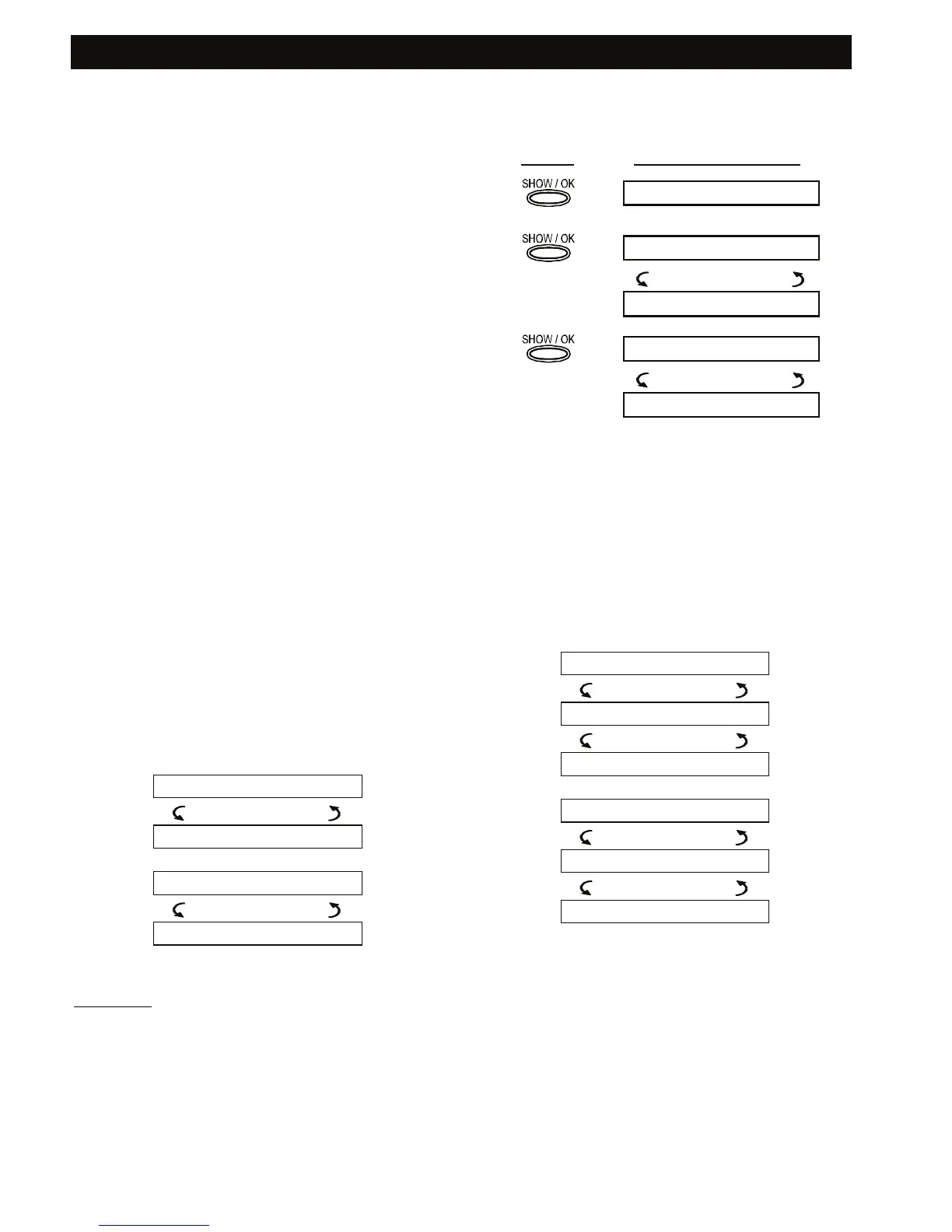
To investigate the source of trouble, proceed as
follows:
PRESS
RESULTANT DISPLAY
READY HH:MM
Z09 INACTIVE
(alternating)
KITCHEN
Z15 LOW BATTERY
(alternating)
LIVING ROOM
In response to further clicking of <SHOW/OK>, the
display will show details of other troubles (if any), or
will revert to the initial alternating displays (see
example above).
Reviewing Memory & Troubles at
the Same Time
If alarms / tamper events are retained in the alarm
memory and at the same time a state of trouble
exists, the display will behave as shown below:
READY HH:MM
(alternating)
READY MEMORY
(alternating)
READY TROUBLE
or, if the system is not ready for arming -
NOT READY HH:MM
(alternating)
NOT READY MEMORY
(alternating)
NOT READY TRBL
Note: When a voice message is in memory, the MSG
display will also appear (as shown in Chapter 3 -
Recording a Message).
To read status information - memory data, open zones
and trouble sources (in this order) - click the <SHOW /
OK> button repeatedly. The memory content will be
displayed first, in the same manner shown in Chapter
5 - Reviewing Alarm / Tamper Memory. If the system
is not ready, open zone information will follow in the
same manner as shown in Chapter 2 - Preparing to
Arm. Trouble sources will be displayed last, in the
same manner shown in Chapter 5 - Reviewing
Trouble Information.