28 D-302754
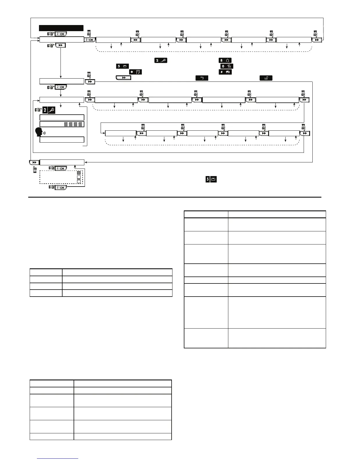
9. DEFINE VOICE
(see figure 4.1a)
HOUSE IDENTITY
USER #5 NAME USER #6 NAME USER #7 NAME USER #8 NAME
RECORDING ENDED
TALK NOW
RECORD A MESSAGE
(e.g. “John’s house”)
(*) (*)
- don’t release
Release button [2]
(**)
Record users 5 - 8 names (for example, David, Rose, Mark, etc.).
The process is identical to HOUSE IDENTITY recording process.
USER TERM #1 USER TERM #2 USER TERM #3 USER TERM #4 USER TERM #5
Record users terms 1-5 (e.g. Living room, Library, etc.), identical to HOUSE IDENTITY recording process.
RECORD SPEECH
No Voice Box
Voice Box Only
Voice Box Mixed
VOICE BOX MODE
(*) RECORD MESSAGE is displayed momentarily. The dark square boxes slowly disappear,
one by one, until end of recording time.
(**) To check the recorded message, press the key and listen to the playback.
CUST. ZONES NAME
EDIT USER TERM 1 EDIT USER TERM 2 EDIT USER TERM 3 EDIT USER TERM 4 EDIT USER TERM 5
To edit User Terms, use the following buttons on the control panel keypad:
press to scroll backward; press to scroll forward ;
press to change from small caps to big caps; press to delete a character / add a space
press to move to the front of the field; press to move to the end of the field
press to move to the next letter; press to move backward; press to clear the field
Figure 4.9 - Speech Recording Flow Chart
4.10 DIAGNOSTIC TEST
This mode allows you to test the function of all protected
area wireless sensors / wireless sirens / wireless keypads /
GPRS / LAN connection / options for resetting the
Broadband Module and to receive / review information
regarding the received signal strength.
The diagnostic test process is shown in figure 4.10.
For WL Sensors / WL Sirens / WL Keypads:
Three reception levels are sensed and reported.
Received Signal Strength Indication:
Reception Buzzer Response
Strong Happy Tune twice ( - - - –––– ) ( - - - ––––)
Good Happy Tune ( - - - –––– )
Poor Sad tune ( –––––––– )
IMPORTANT! Reliable reception must be assured. Therefore,
a "poor" signal strength is not acceptable. If you get a
"poor" signal from a certain wireless unit, re-locate it and re-
test until a "good" or "strong" signal strength is received. This
principle should be followed during the initial testing and also
throughout subsequent system maintenance.
4.10.1 GPRS Communication Test
The GPRS Communication diagnostic procedure tests
GSM/GPRS communication and reports the diagnostic
result. In case of communication failure, detailed
information of the failure is reported.
The following GSM/ GPRS messages are reported:
Message Description
Unit is OK GSM / GPRS is functioning correctly.
GSM comm.
loss
The GSM/GPRS module does not
communicate with the Panel
Pin code fail Missing or wrong PIN code.
(Only if SIM card PIN code is enabled.)
GSM net. fail Unit failed with registration to local
GSM network.
SIM card fail SIM not installed or SIM card failure.
Message Description
GSM not
detected
GSM auto enroll failed to detect
GSM/GPRS module.
No GPRS
service
The SIM card does not have the GPRS
service enabled.
GPRS conn.
fail
Local GPRS network is not available
or, wrong setting to GPRS APN, user
and/or password.
Srvr
unavailable
IPMP Receiver cannot be reached –
Check the Server IP
IP not defined Server IP #1 and #2 are not configured.
APN not
defined
APN is not configured.
SIM card
locked
After entering a wrong PIN code 3
consecutive times the SIM is locked.
To unlock it enter a PUK number. The
PUK number cannot be entered by the
PowerMaxComplete.
Denied by
server
The IPMP denies the connection
request. Check that the Panel is
registered to the IPMP Receiver.
4.10.2 LAN Connection Test
The LAN Connection diagnostic procedure tests
Broadband Module communication to the IPMP and
reports the diagnostic result. In case of communication
failure, detailed information of the failure is reported.
If the Broadband Module is not registered to the
PowerMaxComplete, the menu "LAN CONNECT.TEST"
will not be displayed.