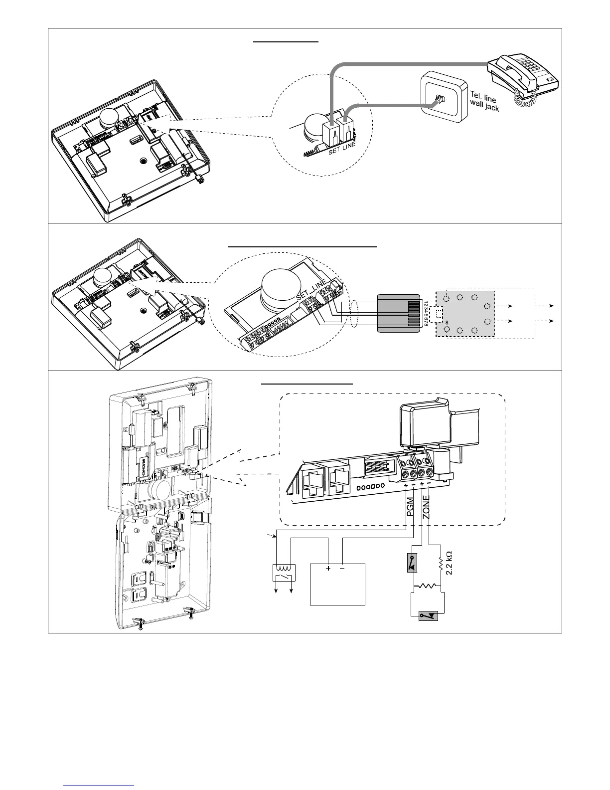
EasyManuals Logo
Home>Visonic>Security System>POWERMAXEXPRESS

Visonic POWERMAXEXPRESS Installer's Guide

Visonic POWERMAXEXPRESS
45 pages
To Next Page IconTo Next Page
To Previous Page IconTo Previous Page
Page #8 background imageLoading...
Page #8 background image
8 D-303973 PowerMaxExpress Installer's Guide
Connect telephone cable to SET connector and telephone line cable to LINE connector (through the desired wiring cable entry).
PHONE WIRING
PHONE WIRING IN NORTH AMERICA
HOUSE
PHONES
RJ-31X
BROWN
GRAY
GRN
RED
LINE
FROM
STREET
1
2 3
4
5
6
7
RJ-31X JACK
RJ-31X
CORD
8-POSITION
RJ-31X PLUG
GRAY
BROWN
GREEN
RED
Relay
PGM output
Vmax=30v
Imax=100mA
External
power supply
5 - 30VDC
PGM & ZONE WIRING
Device
2.2 k
Tamper
Alarm
Figure 3.2 - Wiring
WARNING! When plugging SIREN & ZONE terminals
back into place, be sure to align them carefully with the
pins on the PCB. Misaligned or reverse insertion of
terminals may damage internal PowerMaxExpress circuits!
3.6 Backup Battery Insertion
Connect battery pack as shown in the next drawing.

Table of Contents

Other manuals for Visonic POWERMAXEXPRESS

Questions and Answers:

Question and Answer IconNeed help?

Do you have a question about the Visonic POWERMAXEXPRESS and is the answer not in the manual?

Visonic POWERMAXEXPRESS Specifications

General IconGeneral
BrandVisonic
ModelPOWERMAXEXPRESS
CategorySecurity System
LanguageEnglish

Related product manuals