6
InStallatIon InStructIonS: InStallatIon of SyStem:
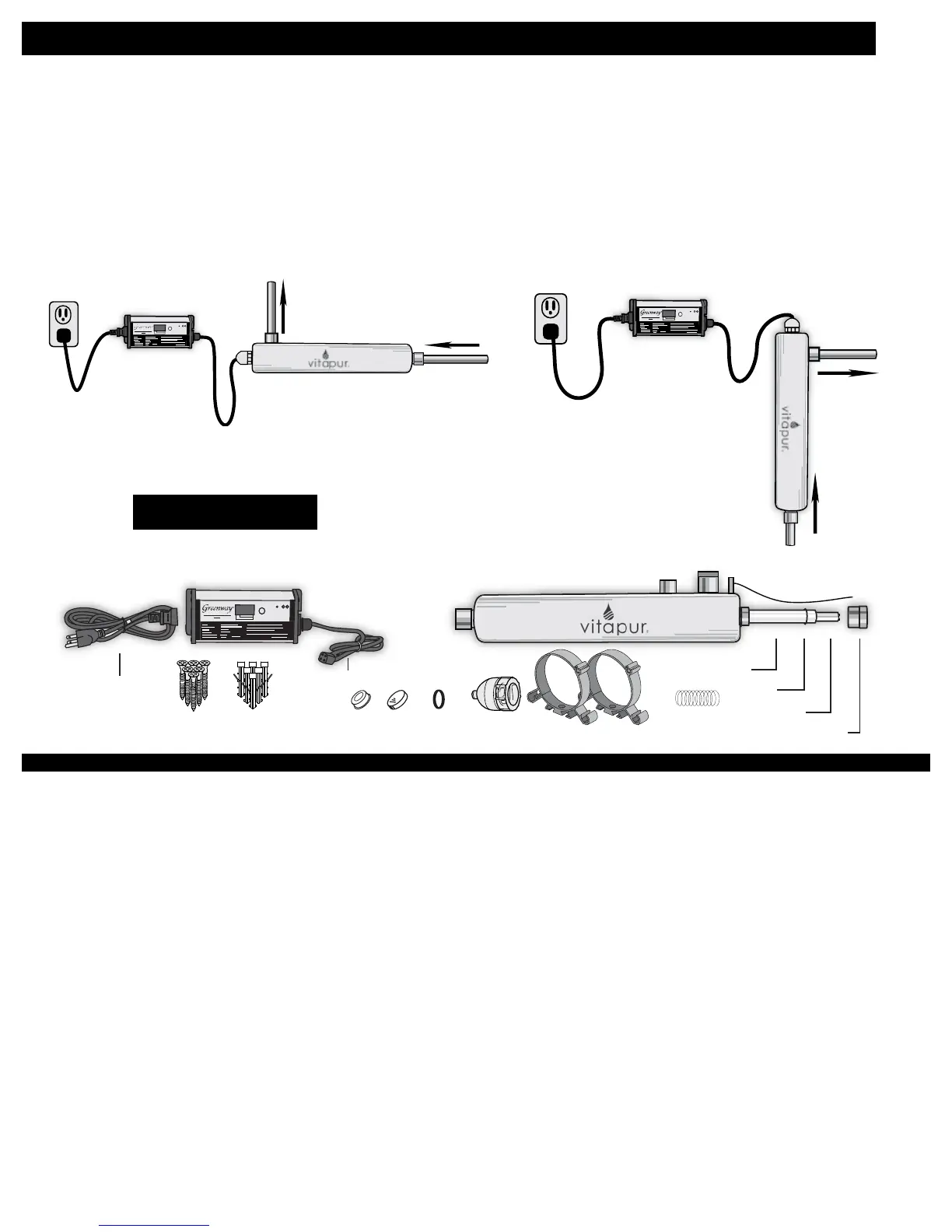
Electronic Control
Ballast
UV Reaction Chamber
Treated
Water
Exits
GFCI
Water Supply
Horizontal installation
• System Orientation – Vitapur
®
Advance UV systems should be installed either horizontally
or vertically, with the outlet port at the top of the system and the inlet port at the base, as
shown in the diagrams below.
Ensure ballast is kept dry and away from any potential condensation. Use drip loops so moisture
does not run down lamp harness or power cord and into ballast.
Prior to installation, remove protective caps from inlet and outlet ports of the UV reaction chamber.
Ballast
UV Reaction
Chamber
Treated
Water
Exits
GFCI
Water
Supply
Veritcal installation
partS breakdown:
When handling the UV lamps and quartz sleeves, soft gloves or a cloth should always be used to prevent
oil deposits on the surface. Oil deposits from your hands can create hot spots on the surface which may
lead to premature bulb failure.
• Determine a suitable location and ensure mounting of the UV system in the correct orientation can be
completed.
• Attach the mounting clamp to the installation structure using an appropriate screw type for both the
weight and material of the surface.
• Position the UV reactor chamber into the mounting clamp and secure.
• Install all inlet / outlet plumbing to the system (inclusive of all pre-ltration and valve set-ups described above.
• Mount the electronic ballast in a dry location close to the UV reaction chamber. Install power cord
and lamp harness using drip loops (see illustration on previous page) to prevent moisture from travelling
along cable and into ballast. If system is a Class A system remove plug, glass insert and O-ring. Screw
OWL sensor with O-ring into sensor port and tighten. Care should be taken not to twist or pull sensor wire
during tightening. Mount OWL controller as specied in OWL manual.
• Ensure the quartz sleeve is intact and that both the silicone o-ring, VuCap retaining ring and retaining nut
are in position and tightened (do not overtighten the retaining nuts, these should be hand tightened only).
• Connect the four pins of the UV lamp to the UV lamp plug on the ballast.
• Insert the UV lamp into the quartz sleeve and secure the VuCap protective cover.
Ballast
UV Chamber
Power Cord
Mounting
Wall
Lamp Connector
Quartz Sleeve
Spring Inside
Quartz Sleeve
Outlet Port
Inlet Port
Cell Clamps
VuCap
Plug Glass
O-Ring
O-Ring
UV Lamp
Retaining Nut
Ground
and Wire
!
Power (green)
Lamp Failure (red)
fIgure 4
 Loading...