VIVOTEK
8 - User's Manual
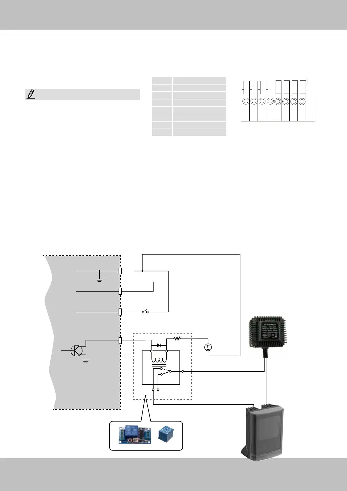
87654321
DI/DO Diagram
1 DC 12V-
2 DC 12V+
3 AC24V_2
4 AC24V_1
5 DI- (GND)
6 DI+
7 DO-
8 DO+ (+12V)
The max. load for power output pin 8,
12V DO, is 50mA.
NOTE:
General I/O Terminal Block
This Network Camera provides a general I/O terminal block which is used to connect external
input / output devices. The pin denitions are described below. The 24V AC can be used as an
alternate power source.
1. The DO+ pin provides a 12V output, and the max. load is 50mA.
2. The max. voltage for DO- pins is 80VDC (External power).
In order to control AC devices, the following diagram can be taken into consideration. This
diagram uses a relay to control the ON/OFF condition of the AC device.
3. An external relay can be triggered by using the DO+ or by an external power source,
depending on the type of relay you use.
4. In case of using an individual relay (instead of using a relay module), for protection against
voltage or current spikes, a transient voltage suppression diode must be connected in parallel
with the inductive load.
DI-
DO+
DI+
DO-
External
power source
VDC
Switch
BJT transistor
Relay
AC
Source
NO NC
External
device