EN-5
English
Network Deployment
4
POW
ER
C
O
LL
I
S
ION
L
I
N
K
RE
CEIVE
PARTITIO
N
1
2
3
4
5
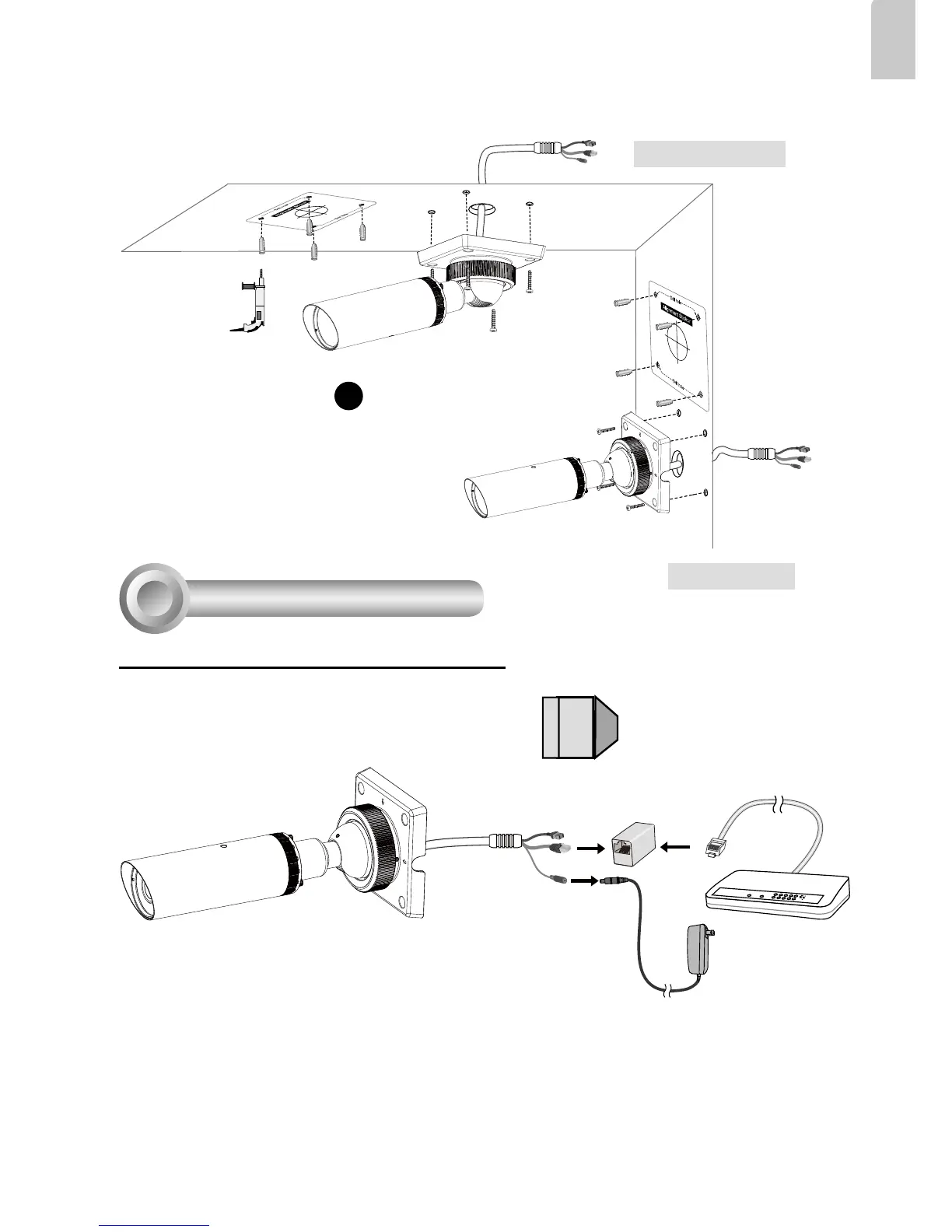
1. If you have external devices such as
sensors and alarms, make connections
from general I/O terminal block.
2. Use the supplied RJ45 female/female
coupler to connect the Network Camera
to a switch.
3. Connect the power cable from the
Network Camera to a power outlet.
GND : Ground
DI : Digital Input
AC24V : 24V-
AC24V : 24V+