VIVOTEK
10 - User's Manual
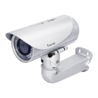
Waterproof Connector
1 DO+ (12V)
2 Digital Output
3 Digital Input 1
4 Ground
5 Digital Input 2
6 Ground
7 TV Out +
8 TV Out -
1
J3
J6
1
8
1
8
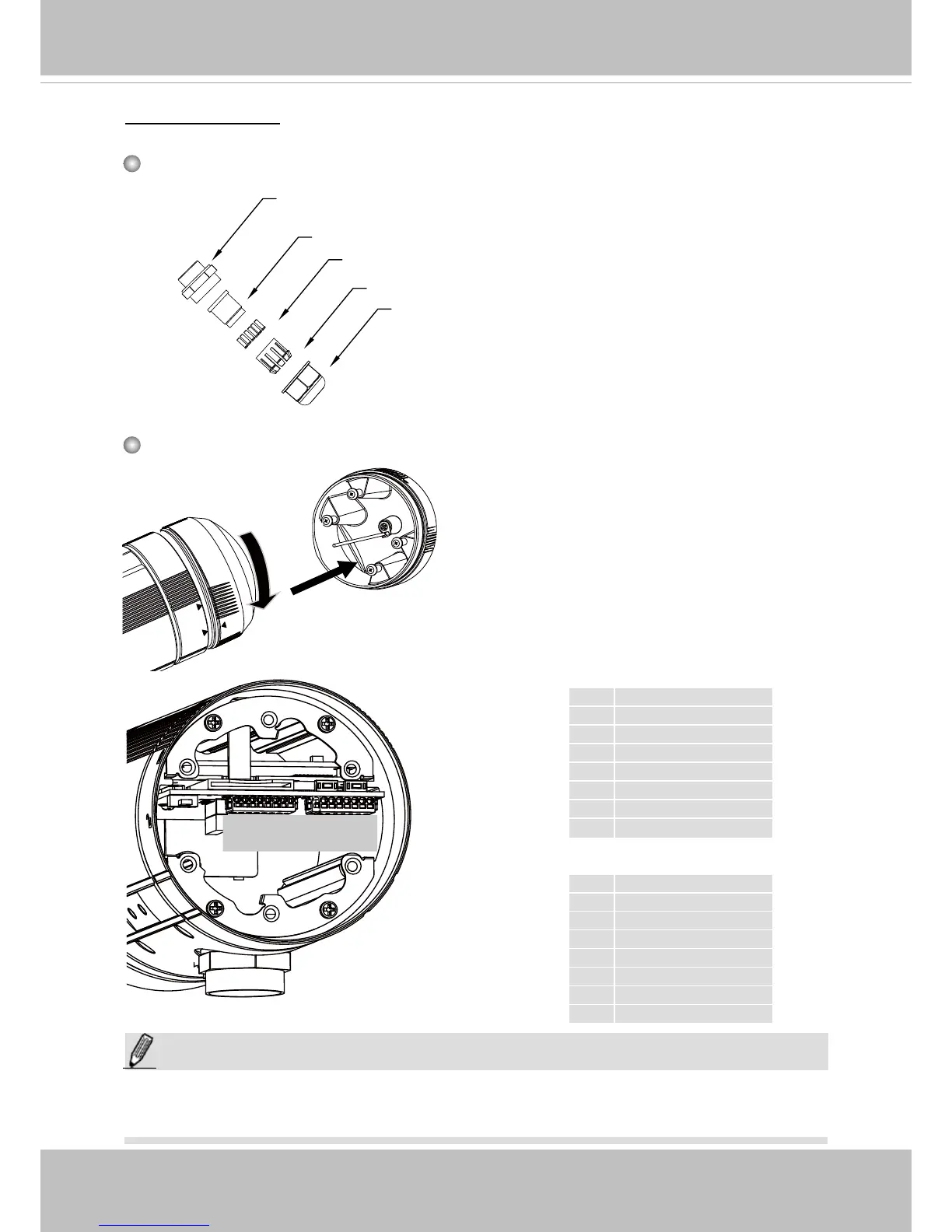
Components of the Waterproof Connector
Seals (C)
Housing (D)
Sealing Nut (E)
Seal (B)
Screw Nut (A)
Pin Denitions
J3
1 Ext. MIC
2 Audio Ground
3 Audio Line out
4 Audio Ground
5 Ground
6 DC 12V+
7 AC24V-
8 AC24V+
J6
NOTE:
In addition to PoE (Power over Ethernet), you can also supply power to the camera using
pins #5~#8 from the terminal block J6, either using DC 12V or AC24V.
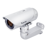
Fix
Align
Open the rear cover by rotating to the
alignment mark, and pull the cover off the
canister.