VIVOTEK
18 - User's Manual
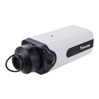
Internet connection via a router
Before setting up the Network Camera over the Internet, make sure you have a router and
follow the steps below.
1. Connect your Network Camera behind a router, the Internet environment is illustrated below.
Regarding how to obtain your IP address, please refer to Software Installation on page 20 for
details.
IP address : 192.168.0.3
Subnet mask : 255.255.255.0
Default router : 192.168.0.1
IP address : 192.168.0.2
Subnet mask : 255.255.255.0
Default router : 192.168.0.1
LAN (Local Area Network)
Router IP address : 192.168.0.1
WAN (Wide Area Network )
Router IP address : from ISP
Cable or DSL Modem
POWER
COLLISION
LINK
RECEIVE
PARTITION
1
2
3
4
5
Internet
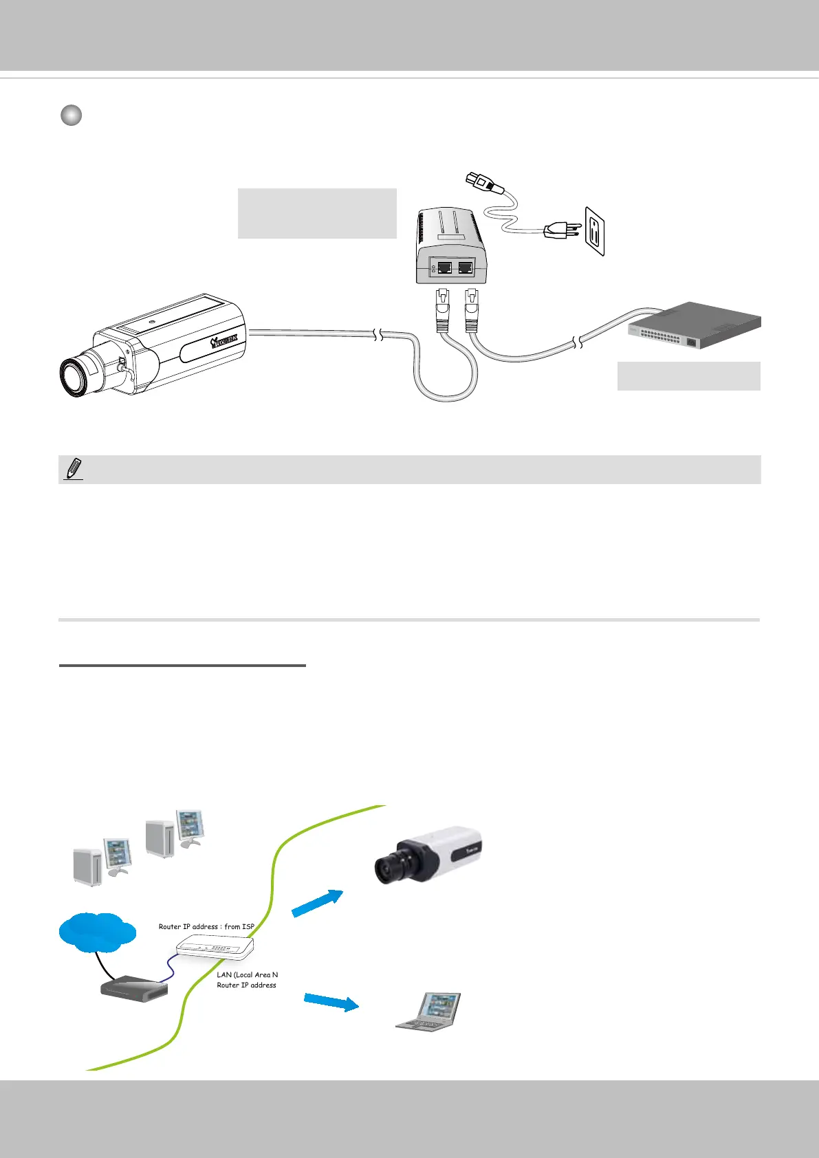
When using a non-PoE switch
Use a PoE power injector (optional) to connect between the Network Camera and a non-
PoE switch.
PoE Power Injector
(optional)
NOTE:
1. The camera is only to be connected to PoE networks without routing to outside plants.
2. For PoE connection, use only UL listed I.T.E. with PoE output.
1. La caméra ne doit être raccordée qu’à des réseaux PoE, sans routage vers des installations
extérieures.
2. Pour les raccordements PoE, utilisez uniquement un équipement de TI homologué UL, avec une sortie
PoE.
Non-PoE Switch