05TA Service Manual
INSTALLING YOUR TUBE-ICE
®
MACHINE
7/19/13
3-5
Wiring and Electrical Connection
! WARNING !
Only service personnel experienced in refrigeration and qualified to work with high voltage
electrical equipment should be allowed to install or work on the Tube-Ice
®
machine.
! WARNING !
Refer to TABLE 3-2 below to properly size wiring connections. A fused disconnect must be
provided near the Tube-Ice
®
machine. Connect 3 phase power to the power distribution block (PDB)
for operation of the Tube-Ice
®
machine and its controls. Rotation checking of cutter motor and water
pump is required (see following section). Also, if one leg of the 3 phase power is higher or lower
(“Wild”), then it should be connected to terminal #L2. Connect the “Ground” wire to the “Ground”
lug provided.
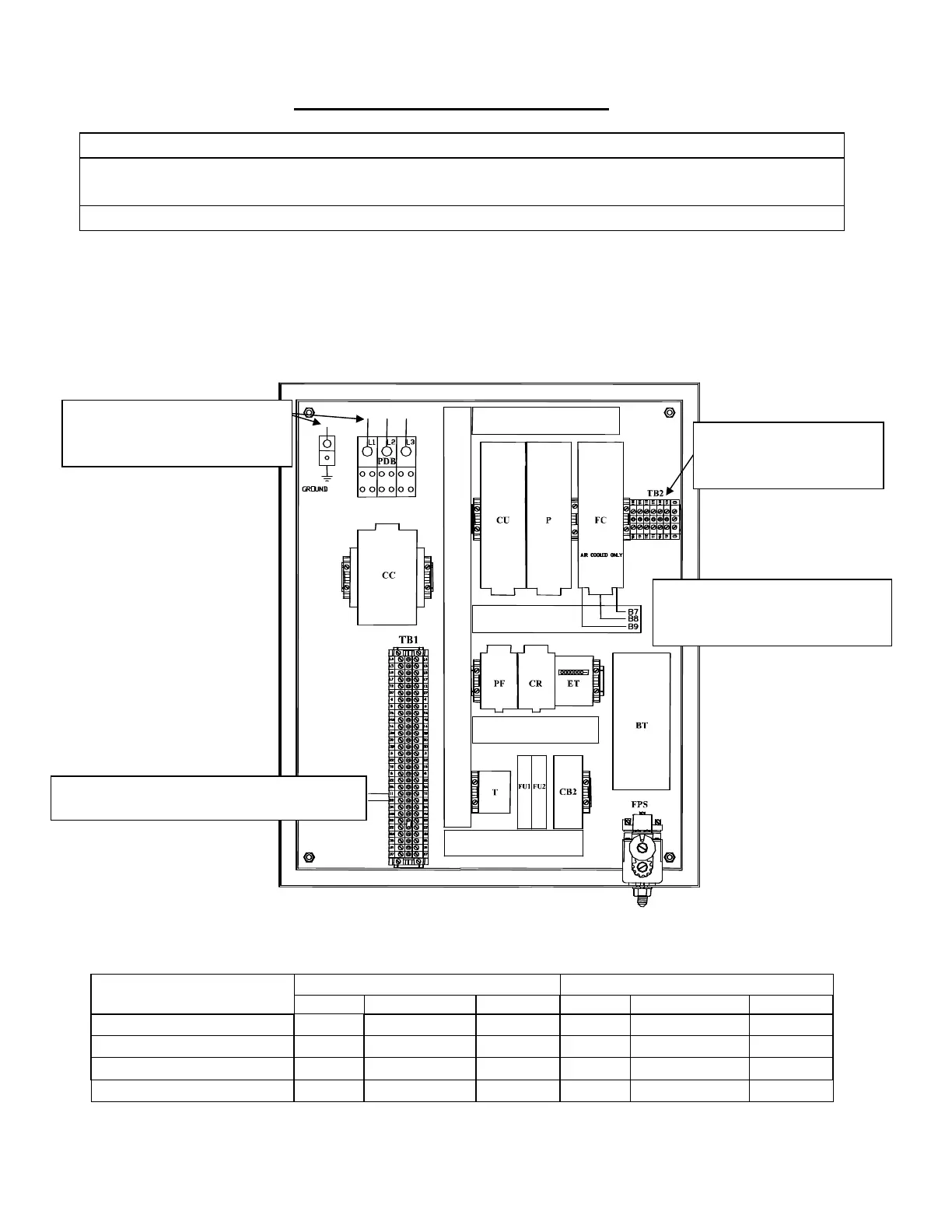
FIGURE 3-3
Control Panel Power Connections
Water Cooled Air Cooled
Standard Voltages
F.L.A. Min. Ampacity
Max. Fuse
F.L.A. Min. Ampacity Max. Fuse
208/230, 3ph, 60 Hz
66.9 81.8 145 80.9 95.8 160
460, 3ph, 60 Hz
32.7 39.9 70 39.7 46.9 80
220, 3ph, 50 Hz
67.5 82.4 145 81.5 95.8 160
400, 3ph, 50 Hz
33.2 40.4 70 40.2 47.4 80
TABLE 3-2
Electrical Specifications
AUX CONNECTIONS
Cutter Motor, Pump Motor
& Compressor Interlocks
MAIN MACHINE POWER
Incoming power to be connected to
Power Distribution Block (PDB)
AIR COOLED CONDENSER
CONNTECTIONS
Power for Fan Motors (B7, B8 & B9)
AIR COOLED CONDENSER CONNTECTIONS
Power for Condenser control circuit (11 & 22)
 Loading...