32
Compact
SECTION 8 WIRING DIAGRAMS
Fig. 29
Fig. 29A
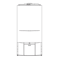
8.1 CONNECTION OF A ROOM THERMOSTAT
(fig. 29 & 29A)
Isolate the appliance from the electrical supply.
Remove the appliance casing and PCB cover.
Connect the room thermostat as shown in diagram
fig. 29. A neutral supply can be taken from the
appliance terminal strip if required. Carry out the
electrical checks as described in section 7.11
prior to refitting the PCB cover and appliance
casing.
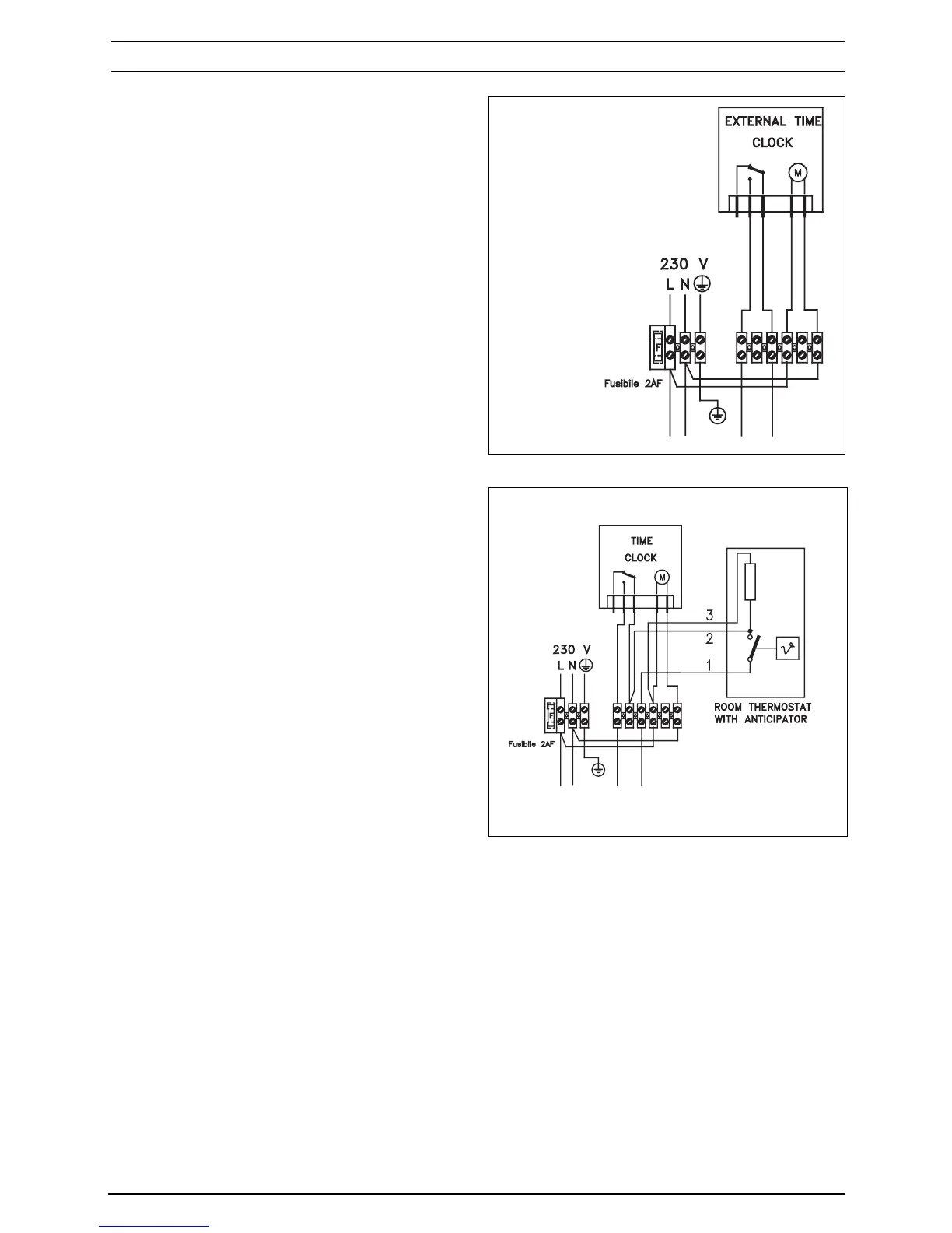
8.2 CONNECTION OF AN EXTERNAL TIME
CLOCK
Should the integral time clock be unsuitable,
additional or alternative controls must be
connected to the appliance terminal strip as shown
in fig. 29 & 29A.
NOTE
Guidance on the recommended practice for the
installation of external controls, can be found in
CHeSS – HC1/HC2 (www.energy-
efficiency.gov.uk).