33
Compact
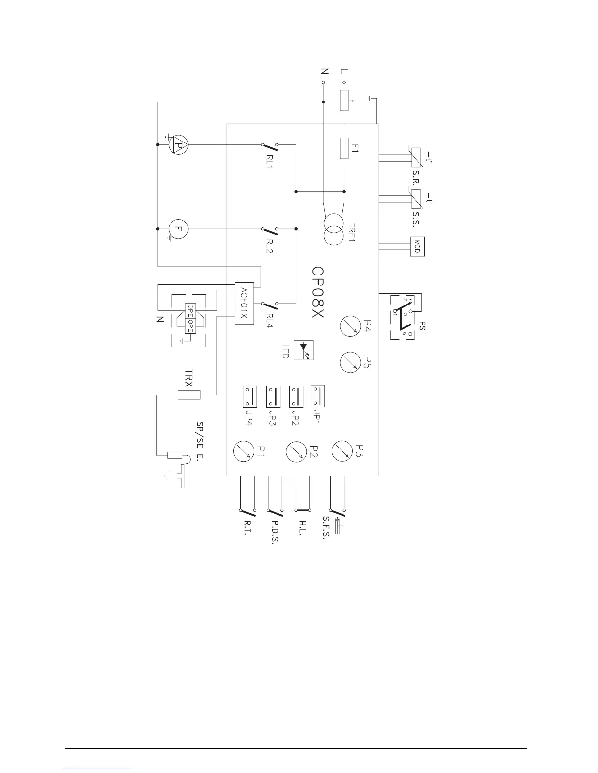
FUNCTIONAL DIAGRAM
NOTE: L-N-E CONNECTION IS ADVISABLE
Key
R.T. Room thermostat
S.F.S. Domestic hot water flow switch
P.S. Pressure switch
P.D.S. Differential pressure switch
H.L. High limit thermostat
S.R. Heat thermistor
S.S. Domestic hot water thermistor
MOD Modulator
F Fan
P Pump
SP/SE E. Spark\Sense electrode
OPE Gas valve solenoids
B.C.B. Burner control board
CP08X Boiler control board
JP2 Setting timer
JP3 Natural gas or L.P.G. selector
JP4 Jumper disable/enable DHW absolut thermostat
P1 Domestic hot water temperature control
P2 Central heating temperature control
P3 Off/summer/winter selector
P4-P5 Setting trimmer
F External fuse 2 A F (on 230 V circuit)
F2 (CP08X) Fuse 2 A F (on 230 V circuit)
RL1 Ignition relay
RL2 Fun relay
RL4 Pump relay
TRF1 Trasformer
TRX Ignition trasformer
ACF01X Ignition control board
LED Led OK (green)
Led alarm (red)
Combustion test (blink orange)
Fig. 30