Supplied By www.heating spares.co Tel. 0161 620 6677
10
Linea
Horizontal flue terminals and accessories
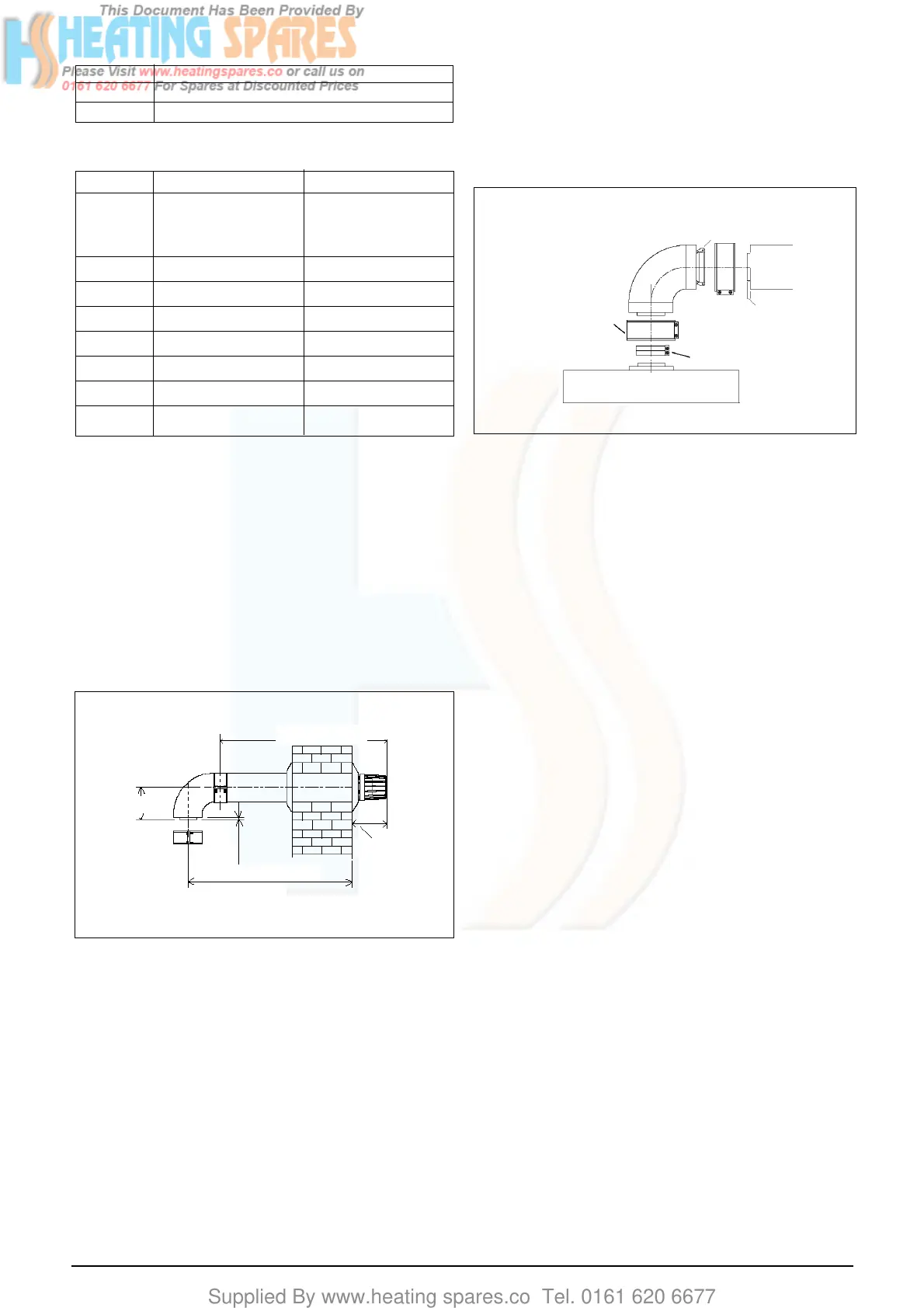
Part No. Description Min-Max Length
2359029 Standard flue kit. For 833mm
use with add. Bends & (dimension ‘X’)
extensions
2359119 Telescopic flue kit.
2359069 750mm extension 750mm
2359079 1500mm extension 1500mm
2359089 Telescopic extension 350 – 490mm
2359049 45° bend (pair) N/A
2359059 90° bend N/A
0225760 Wall bracket (5) N/A
Bend Reduction in maximum flue length for each bend
45° bend 0.5 metre
90° bend 1.0 metre
Fig. 7
Reduction for additional bends
Using the template provided, mark and drill a
107mm hole for the passage of the flue pipe. The
hole should have a 1° drop from the boiler to out-
side, to eliminate the possibility of rainwater en-
tering the appliance via the flue.
The fixing holes for the wall-mounting bracket/
fixing jig should now be drilled and plugged, an
appropriate type and quantity of fixing should be
used to ensure that the bracket/jig is mounted
securely. Once the bracket/jig has been secured
to the wall, mount the appliance onto the bracket.
4.5.1.1 FITTING THE HORIZONTAL FLUE KIT (see
4.5.1)
Carefully measure the distance from the centre
of the appliance flue outlet to the face of the
outside wall (dimension ‘X’ see fig. 7). Ensure
the inner (60mm) pipe is fully inserted into the
outer (100mm) pipe (when the inner pipe is fully
inserted, it stands proud of the outer pipe by
7.5mm). Add 32mm to dimension ‘X’ to give the
overall flue length (dimension ‘Y’).
NOTE
The standard horizontal flue kit (part no.
2359029) is suitable for a distance (dimension
‘Y’) of up to 865mm.
The telescopic flue kit (part no. 2359119) is suit-
able for a distance (dimension ’Y’) of up to
600mm.
Dimension ‘Y’ is measured from the end of the
terminal to the end of the outer (100mm) pipe.
The internal trim should be fitted to the flue pipe
before connection of the 90° bend.
Using the dimensions given in fig. 9 as a refer-
ence, mark and cut a 105mm hole in the ceiling
and/or roof.
Fit the appropriate flashing plate to the roof and
insert the vertical flue terminal through the flash-
ing plate from the outside, ensuring that the col-
lar on the flue terminal fits over the flashing.
The fixing holes for the wall-mounting bracket
should now be drilled and plugged, an appropri-
ate type and quantity of fixing should be used to
ensure that the bracket is mounted securely.
Once the bracket has been secured to the wall,
mount the appliance onto the bracket
If the horizontal flue kit (2359029) requires to be
cut to the correct size (dimension ‘Y’), you must
ensure that the inner (60mm) pipe stands proud
of the outer (100mm) pipe by 7.5mm (see fig. 8).
Ensure any burrs are filed or removed and that
any seals are located properly before assembly.
The telescopic flue terminal should be adjusted
to the appropriate length and then fixed using the
securing screw supplied.
4.5.1.2 STANDARD FLUE KIT (2359029)
Hold the inner (60mm) pipe of the terminal as-
sembly and connect to the push-fit end of the 90°
bend (supplied) using a twisting action. Insert
the assembled flue into the previously drilled hole.
Using the clips & screws supplied, connect the
flue assembly to the boiler, ensuring that the ter-
minal protrudes past the finished outside wall by
the correct length (135mm).
4.5.1.3 TELESCOPIC FLUE KIT (2359119)
Connect the 60mm push-fit connection of the flue
bend (supplied) to the telescopic flue assembly
using a twisting action. Insert the assembled flue
into the previously drilled hole. Using the clips &
screws supplied, connect the flue assembly to
the boiler, ensuring that the terminal protrudes
past the finished outside wall by the correct length
(135mm).
Fig. 8
Dimension “Y”
Dimension “X”
Max 833 mm
135 mm
7,5
110
Boiler
Push-fit connection
Terminal or
extension
7,5 mm
Inner 60mm clip
Outer 100mm clip
 Loading...