EasyManua.ls Logo

Volkswagen Taro 1989 User Manual

Volkswagen Taro 1989
186 pages
To Next Page IconTo Next Page
Page #1 background imageLoading...
Page #1 background image
VA.G
Service.
Workshop
Manual
Volkswagen Taro
1989
b
1.8
and
2.2
Itr.
I
BOO
klet
Earburetor engines
I
Edition 02.89
Service Department. Technical Information

Table of Contents

Question and Answer IconNeed help?

Do you have a question about the Volkswagen Taro 1989 and is the answer not in the manual?

Volkswagen Taro 1989 Specifications

General IconGeneral
Engine TypeDiesel
Displacement2.4 L
Cylinders4
Valves per Cylinder2
Power Output54 kW

Summary

IDENTIFICATION INFORMATION

ENGINE SERIAL NUMBER

Serial number location on cylinder block.

GENERAL REPAIR INSTRUCTIONS

Non-reusable parts

Indicates parts that must be replaced with new ones.

Precoated parts

Details on precoated parts and recoating procedures.

Use of special service tools (SST) and special service materials (SSM)

Importance of using specified tools and materials for repairs.

Care must be taken when jacking up and supporting the vehicle

Precautions for safe jacking and supporting of the vehicle.

Tag hoses before disconnecting them

Importance of tagging hoses for correct reconnection.

REMOVE AND FIT ENGINE

STANDARD BOLT TORQUE SPECIFICATIONS

HOW TO DETERMINE BOLT STRENGTH

Guide to identifying bolt strength classes based on markings.

SPECIFIED TORQUE FOR STANDARD BOLTS

SSM (SPECIAL SERVICE MATERIALS)

ENGINE MECHANICAL

SPECIFICATIONS

Technical specifications for tune-up, coolant, and oil capacity.

SPECIFICATION (CONT'D)

Intake manifold vacuum

Specification for intake manifold vacuum at idle and 400mm Hg.

Compression pressure

Specification for compression pressure at 250 rpm.

Cylinder head

Specifications for cylinder head warpage, valve seat, and angle.

Valve guide bush

Specifications for valve guide bush inside diameter.

Valve

Specifications for valve overall length and stem diameter.

Valve spring

Specifications for valve spring free length and installed tension.

Rocker arm and shaft

Specifications for rocker arm diameter and oil clearance.

Push rod

Specification for push rod circle runout.

Chain and sprocket

Specifications for chain slack and elongation.

SPECIFICATIONS (CON' T'D)

Tensioner and damper

Specifications for tensioner head thickness and damper thickness.

Valve lifter

Specifications for valve lifter diameter and oil clearance.

Camshaft

Specifications for camshaft thrust clearance and journal diameter.

Cylinder block

Specifications for cylinder head warpage and bore diameter.

SPECIFICATIONS (CONT'D)

Piston and ring

Specifications for piston diameter and oil clearance.

Piston ring groove clearance

Specification for piston ring groove clearance.

Piston ring end gap

Specifications for piston ring end gap.

Connecting rod

Specifications for connecting rod thrust clearance and bearing thickness.

SPECIFICATIONS (CONT'D)

Connecting rod (cont'd)

Specifications for connecting rod oil clearance.

Crankshaft

Specifications for crankshaft thrust clearance and journal diameter.

TORQUE SPECIFICATIONS

TROUBLESHOOTING

ENGINE OVERHEATING

Causes and remedies for engine overheating.

HARD STARTING

Causes and remedies for engine starting problems.

ROUGH IDLING

ENGINE MISFIRES/POOR ACCELERATION

Causes and remedies for engine misfires and poor acceleration.

ENGINE HESITATES/POOR ACCELERATION (CONT'D)

ENGINE DIESELING

BACKFIRE

BACKFIRE (CONT'D)

EXCESSIVE OIL CONSUMPTION

EXCESSIVE FUEL CONSUMPTION

UNPLEASANT ODOR

ENGINE TUNE-UP

INSPECTION OF ENGINE COOLANT

Procedures for checking and replacing engine coolant.

INSPECTION OF ENGINE OIL

Procedures for checking engine oil quality and level.

Check engine oil level

INSPECTION OF BATTERY

CLEANING OF AIR FILTER

INSPECTION OF HIGH-TENSION CORDS

INSPECTION OF SPARK PLUGS

INSPECTION OF ALTERNATOR DRIVE BELT

ADJUSTMENT OF IGNITION TIMING

Inspect dwell angle

Checking the dwell angle and its specification.

Adjust ignition timing

Steps for adjusting ignition timing using a timing light.

Further check ignition timing

Additional checks for ignition timing at different RPMs.

ADJUSTMENT OF IDLE SPEED AND IDLE MIXTURE

METHOD WITH CO-METER

Inspect CO-concentration

How to measure and check CO concentration in exhaust.

ALTERNATIVE METHOD

Visually inspect carburetor

Initial conditions

Adjust idle speed and idle mixture

Inspect CO-concentration

ADJUSTMENT OF FAST IDLE SPEED

ADJUSTMENT OF THROTTLE POSITIONER SETTING SPEED

COMPRESSION CHECK

PREPARATION FOR REMOVAL

REMOVAL OF CYLINDER HEAD

DISASSEMBLY OF CYLINDER HEAD

INSPECTION AND CLEANING OF CYLINDER HEAD COMPONENTS

Inspect head for flatness

Measuring cylinder head warpage using a straight edge.

Inspect cylinder head for cracks

Inspecting the cylinder head for cracks using a dye penetrant.

Clean valves

Cleaning carbon from valve heads and surfaces.

Inspect valve stems and valve guide bushes

Measuring valve stem and guide bush dimensions.

If necessary, replace valve guide bush

Inspect and grind valves

Check the valve overall length

Inspect and clean valve seats

Inspect valve springs

Inspect rocker arm and shaft

Inspect push rods

Inspect intake and exhaust manifolds

ASSEMBLY OF CYLINDER HEAD

Assemble Intake and exhaust manifolds

Assembling intake and exhaust manifolds.

Install intake and exhaust manifolds

Installing intake and exhaust manifolds.

Install carburetor

Installing the carburetor.

INSTALLATION OF CYLINDER HEAD

Fit push rods and rocker shaft assembly

Installing push rods and the rocker shaft assembly.

Fit cylinder head cover

Installing the cylinder head cover.

Fit tubes and spark plugs

Installing spark plug tubes and spark plugs.

AFTER INSTALLATION

PREPARATION FOR REMOVAL

REMOVAL OF TIMING CHAIN AND CAMSHAFT

Remove timing chain cover

Removing the timing chain cover.

Check timing chain slack

Measuring and checking timing chain slack.

Remove chain tensioner

Removing the timing chain tensioner.

Remove timing chain and sprockets

Removing the timing chain and sprockets.

Remove vibration damper

Remove thrust plate and camshaft

Inspect chain and sprocket

Inspect chain tensioner

If necessary, replace chain tensioner plunger

Inspect chain vibration damper

Inspect valve lifters

If necessary, bleed valve lifters

INSTALLATION OF TIMING CHAIN AND CAMSHAFT

Fit timing chain and sprockets

Installing the timing chain and sprockets with timing marks aligned.

Fit chain tensioner

Installing the timing chain tensioner.

Fit timing chain cover

Installing the timing chain cover with a new gasket.

Fit crankshaft pulley

Fit valve lifters

AFTER INSTALLATION

PREPARATION FOR DISASSEMBLY

DISASSEMBLY OF CYLINDER BLOCK

Check connecting rod thrust clearance

Measuring connecting rod thrust clearance.

Remove connecting rod caps and check oil clearance

Removing rod caps and checking oil clearance.

Remove the connecting rod cap

Remove piston and connecting rod assemblies

Check crankshaft thrust clearance

Remove main bearing caps and check oil clearance

Remove crankshaft

INSPECTION OF CYLINDER BLOCK

Remove scoring from cylinder bore

Removing scoring from cylinder bores.

DISASSEMBLY OF PISTON AND CONNECTING ROD ASSEMBLIES

Disconnect connecting rod from piston

Disconnecting connecting rod from piston using SST.

INSPECTION OF PISTON AND CONNECTING ROD ASSEMBLIES

Inspect piston diameter and oil clearance

Measuring piston diameter and oil clearance.

Inspect clearance between wall of piston ring groove and new piston ring

Inspect piston ring end gap

Inspect connecting rods

BORING OF CYLINDERS

Keep oversized pistons

List of oversized piston diameters.

Calculate dimension for boring cylinders

Formula for calculating cylinder boring dimensions.

INSPECTION AND REPAIR OF CRANKSHAFT

Inspect main journals and crank pins

Checking main journals and crank pins for taper and roundness.

INSPECTION AND REPAIR OF CAMSHAFT BEARINGS

If necessary, replace camshaft bearings

Procedures for removing and installing camshaft bearings.

INSPECTION OF VALVE LIFTER BORES

REPLACEMENT OF CRANKSHAFT REAR OIL SEAL

ASSEMBLY OF PISTON AND CONNECTING ROD ASSEMBLIES

Fit bearings

Fitting bearings into connecting rods and rod caps.

ASSEMBLY OF CYLINDER BLOCK

Fit piston and connecting rod assemblies

Installing piston and connecting rod assemblies into cylinders.

Fit connecting rod bearing caps

Fitting connecting rod bearing caps with correct orientation.

Fit rear oil seal retainer

Fit timing chain case

Fit water by-pass pipe

POST ASSEMBLY

Fit flywheel

Installing the flywheel and torquing.

Fit clutch disc and cover

Installing the clutch disc and cover.

FUEL SYSTEM

SPECIFICATIONS

Carburetor specifications for float level, throttle valve angles, etc.

PRECAUTIONS

TROUBLESHOOTING

ON-VEHICLE INSPECTION

Inspect automatic choke system

Checking the automatic choke system operation.

Inspect choke breaker (CB) System

Inspecting the choke breaker system operation.

Inspect auxiliary acceleration pump (AAP) System

Inspect auxiliary acceleration pump (AAP) diaphragm

GENERAL CLEANING PROCEDURE

INSPECTION OF CARBURETOR

Inspect float and needle valve

Inspecting the float and needle valve for wear or damage.

Inspect power piston

Checking the power piston for smooth movement.

Inspect fuel cut-out solenoid valve (first)

Testing the fuel cut-out solenoid valve for proper function.

Inspect choke heater (coil housing)

Inspect outer vent control valve (OVCV)

REMOVAL OF CARBURETOR

DISASSEMBLY OF CARBURETOR

Remove float end needle valve

Removing the float and needle valve.

Remove needle valve seat

Removing the needle valve seat and gasket.

Remove pump plunger and boot

Removing the pump plunger and boot.

Remove coil housing

Removing the coil housing.

Remove choke breaker (CB)

Removing the choke breaker component.

Remove outer vent control valve (OVCV)

Removing the outer vent control valve.

DISASSEMBLY OF CARBURETOR BODY

Remove primary and secondary small venturies

Removing small venturies from the carburetor.

Remove fuel cut-out solenoid valve

Removing the fuel cut-out solenoid valve.

Remove auxiliary acceleration pump (AAP)

Removing the auxiliary acceleration pump.

Remove hot idle compensator (HIC)

Removing the hot idle compensator.

Remove secondary throttle valve diaphragm

Removing the secondary throttle valve diaphragm.

Disassemble secondary throttle valve diaphragm

Remove sight glass

Separate body and flange

GENERAL CLEANING PROCEDURE

INSPECTION OF CARBURETOR

Inspect float and needle valve

Inspecting the float and needle valve for wear or damage.

Inspect power piston

Checking the power piston for smooth movement.

Inspect fuel cut-out solenoid valve (first)

Testing the fuel cut-out solenoid valve for proper function.

Inspect choke heater (coil housing)

Inspect outer vent control valve (OVCV)

ASSEMBLY OF CARBURETOR

Assemble carburetor body and flange

Assembling the carburetor body and flange with new parts.

Fit sight glass

Fitting the sight glass with new seals.

Assemble secondary throttle valve diaphragm

Assembling the secondary throttle valve diaphragm.

Fit secondary throttle valve diaphragm

Fitting the secondary throttle valve diaphragm.

Fit primary and secondary main air bleeders

Fit main and power jets

Fit check ball and jets

Fit pump filter

Fit throttle positioner

Fit outer vent control valve (OVCV)

Fit choke breaker (CB)

Fit coil housing

Fit boot and pump plunger

Fit needle valve seat

Fit needle valve

Adjust float level

Fit float

Fit air horn assembly

Fit vacuum hose of choke breaker (CB)

Fit vacuum hoses

Connect wire(s) to connector

Check for smooth operation of each part

ADJUSTMENT OF CARBURETOR

Adjust full opening angle of primary throttle valve

Adjusting the primary throttle valve's full opening angle.

Adjust full opening angle of secondary throttle valve

Adjusting the secondary throttle valve's full opening angle.

Adjust kickup angle

Adjust secondary touch angle

Automatik choke

Adjust fast idle angle

Adjust unloader angle

Adjust choke breaker (CB)

Adjust acceleration pump stroke

Preset Idle speed adjusting screw

Preset idle mixture adjusting screw.

INSTALLATION OF CARBURETOR

FUEL PUMP

REMOVAL OF FUEL PUMP

Procedures for disconnecting fuel hoses and removing the fuel pump.

INSPECTION OF FUEL PUMP

INSTALLATION OF FUEL PUMP

DECELERATION FUEL CUT-OUT SYSTEM

Inspect vacuum switch

Checking the vacuum switch for continuity.

Inspect fuel cut-out solenoid valve (First)

Inspecting the fuel cut-out solenoid valve.

FUEL TANK AND LINE

COMPONENTS

Diagram showing fuel tank and line components.

PRECAUTIONS

INSPECT FUEL LINES AND CONNECTIONS

COOLING SYSTEM

SPECIFICATIONS

Specifications for engine coolant capacity and thermostat valve lift.

TORQUE SPECIFICATIONS

TROUBLESHOOTING

WATER PUMP

COMPONENTS

Exploded view of water pump components.

REMOVAL OF WATER PUMP

INSPECTION OF WATER PUMP COMPONENTS

INSTALLATION OF WATER PUMP

THERMOSTAT

REMOVAL OF THERMOSTAT

Procedures for removing the water inlet and thermostat.

INSPECTION OF THERMOSTAT

Checking thermostat valve opening temperature and lift.

INSTALLATION OF THERMOSTAT

RADIATOR

CLEANING OF RADIATOR

Procedures for cleaning the radiator core.

INSPECTION OF RADIATOR

Inspecting the radiator cap for proper function.

Inspect cooling system for leaks

LUBRICATION SYSTEM

SPECIFICATIONS

Specifications for engine oil capacity and oil pressure.

TORQUE SPECIFICATIONS

Torque specifications for lubrication system parts.

TROUBLESHOOTING

Troubleshooting common lubrication system problems.

OIL PRESSURE CHECK

REPLACEMENT OF ENGINE OIL AND OIL FILTER

OIL PUMP

COMPONENTS

Exploded view of oil pump components.

REMOVAL OF OIL PUMP

Procedures for removing the oil pump assembly.

Remove oil pan

Remove oil strainer

Remove oil pump

DISASSEMBLY OF OIL PUMP

Check oil pump operation

Checking the oil pump's relief valve and rotor clearances.

ASSEMBLY OF OIL PUMP

INSTALLATION OF OIL PUMP

IGNITION SYSTEM

SPECIFICATIONS

Specifications for ignition timing, spark plugs, and distributor.

PRECAUTIONS

TROUBLESHOOTING

IGNITION SYSTEM CIRCUIT

ON-VEHICLE INSPECTION

SPARK TEST

Performing a spark test to check for spark occurrence.

INSPECTION OF IGNITION COIL

INSPECTION OF DISTRIBUTOR

Inspect breaker plate

Inspecting the breaker plate for drag.

Inspect governor shaft

Inspecting the governor shaft for roughness or wear.

Inspect cam

REPLACEMENT OF GOVERNOR SHAFT (OR DRIVEN GEAR)

Install governor shaft

Installing the governor shaft with thrust washer.

Install new driven gear

Installing the driven gear and plate washer.

ASSEMBLY OF DISTRIBUTOR

Fit vacuum advancer

Installing the vacuum advancer.

Fit and adjust breaker point

Fitting and adjusting the breaker points.

Fit and adjust damping spring

Fit lead wire and terminal

Fit rotor and dust cover

Fit distributor cap and high-tension cords assembly

Fit new O-ring to distributor housing

INSTALLATION OF DISTRIBUTOR

EMISSION CONTROL SYSTEM

SYSTEM PURPOSE

Overview of emission control systems and their abbreviations.

POSITIVE CRANKCASE VENTILATION (PCV) SYSTEM

INSPECTION OF PCV VALVE

Procedures for removing, inspecting, and reinstalling the PCV valve.

INSPECTION OF PCV HOSES AND CONNECTIONS

Visually inspecting PCV hoses and connections.

THROTTLE POSITIONER (TP) SYSTEM

INSPECTION OF TP SYSTEM

Checking and adjusting the TP system's operation.

Check of control system for vacuum switching valve

Check TP setting speed

INSPECTION OF SPEED SENSOR TO VACUUM SWITCHING VALVE

INSPECTION OF VACUUM SWITCHING VALVE

SPARK DELAY (SD) SYSTEM

INSPECTION OF SD SYSTEM

Checking the vacuum gauge and distributor vacuum advancer.

INSPECTION OF VACUUM TRANSMITTING VALVE (VTV)

AIR SUCTION (AS) SYSTEM

INSPECTION OF AS SYSTEM

Inspecting AS system hoses, reed valve, and vacuum control valve.

AUXILIARY SYSTEMS

FUEL EVAPORATIVE EMISSION CONTROL (EVAP) SYSTEM

Diagram and purpose of the EVAP system.

INSPECTION OF OUTER VENT CONTROL VALVE

INSPECTION OF BIMETAL VACUUM SWITCHING VALVE (BVSV)

Checking the BVSV operation with water and air.

INSPECTION OF CHARCOAL CANISTER

AUTOMATIC HOT AIR INTAKE (HAI) SYSTEM

INSPECTION OF HOT AIR INTAKE SYSTEM

Checking the air control valve operation and hoses.

CHOKE BREAKER (CB) SYSTEM

INSPECTION OF CHOKE BREAKER SYSTEM

Checking the bimetal vacuum switching valve and diaphragm.

INSPECTION OF BIMETAL VACUUM SWITCHING VALVE

Checking the BVSV by blowing air into pipes.

INSPECTION OF JET

INSPECTION OF CHOKE BREAKER DIAPHRAGMS

AUXILIARY ACCELERATION PUMP (AAP) SYSTEM

INSPECTION OF AUXILIARY ACCELERATION PUMP SYSTEM

Checking the AAP system with cold and warm engines.

INSPECTION OF AUXILIARY ACCELERATION PUMP DIAPHRAGM

Checking the AAP diaphragm operation at idle.

INSPECT OF BIMETAL VACUUM SWITCHING VALVE

DECELERATION FUEL CUT SYSTEM

INSPECTION OF DECELERATION FUEL CUT-OUT SYSTEM

Checking system operation and fuel cut-out solenoid.
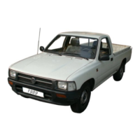
INSPECTION VACUUM SWITCH

Related product manuals