Connection
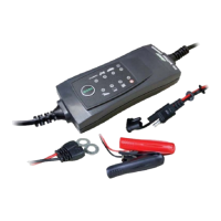
After both input and output are connected, the charger will produce an output after 10sec.
8-PIN connectors
1 +V in:
The voltage of this pin is equal to the input voltage. Installers can wire a switch between this pin and the
“Ignition” pin to remotely turn the unit on or off.
2 Ignition:
Connect this pin to an ignition (+) source to make the charger operate in sync with vehicle ignition
switch.
3 GND:
Ground pin for Remote Display. Connect to the black wire from the display box.
4 Alarm:
Alarm output pin. Alarm output voltage equals to system input voltage with max 200mA current.
5 Yellow:
Connect to display yellow wire.
6 Green:
Connect to display green wire.
7 Red:
Connection to display red wire.
8 T+:
Not used.
 Loading...