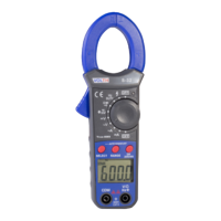
The VOLTH S-32 is a Mini True-RMS AC/DC Clamp Meter designed for a wide range of electrical measurements. It incorporates a high-performance MCU processor, offering high reliability, security, and automatic ranging functionality. This handheld clamp meter features a large digital display, full-range overload protection, data-hold function, undervoltage indication, and an auto shut-off function to conserve battery life.
Function Description:
The S-32 is equipped with TRUE RMS measurement, enabling accurate measurement of frequency voltage and non-sinusoidal voltage. It also includes an inrush current measurement function, capable of measuring inrush currents up to 80mS RMS. This makes it suitable for applications involving frequency-converting power supplies and motor performance testing. The device can measure DC current up to AC and DC 600A, making it versatile for use in electroplating, DC welding machines, motor vehicle testing, and various DC 500mA current measurements. It is presented as a new generation of practical electrical measuring instruments.
The meter is ideal for testing, maintenance, and repairs in various sectors including colleges, smelting, communications, manufacturing, petroleum, electric power, national defense, and electronic equipment.
Important Technical Specifications:
- Display: LCD, maximum display 3999.
- Jaw Span: Maximum 30mm.
- Auto Negative Polarity Indication: Displays "-".
- Low Battery Indication: Displays battery symbol.
- Auto Power Off: After 10 minutes of inactivity, the instrument enters sleep mode. This can be overridden by holding the DH key during power-on.
- Work Environment: 0°C to 40°C, 75% RH.
- Storage Environment: -10°C to 60°C, 85% RH.
- Battery: 9V x 1 (IEC6F22, NEDA1604 or JIS006P).
- External Dimensions: 195(L) × 64(W) × 35(H) mm.
- Weight: Approximately 360g (including battery).
- Accuracy: ±(% reading + digit); calibration term is one year.
- Ambient Temperature for Accuracy: 23°C ± 5°C; Ambient Humidity: ≤70% RH.
DC Voltage (DCV):
- Range: 400mV, 4V, 40V, 400V, 600V
- Accuracy: ±(0.8%+2d) for 400mV-400V, ±(1%+3d) for 600V
- Resolution: 0.1mV, 1mV, 10mV, 100mV, 1V
AC Voltage (ACV):
- Range: 400mV, 4V, 40V, 400V, 600V
- Accuracy: ±(1.2%+5d) for 400mV-400V, ±(1.5%+5d) for 600V
- Resolution: 0.1mV, 1mV, 10mV, 100mV, 1V
- Frequency: 10Hz~1kHz (square wave accuracy 10Hz to 400Hz).
- Display: TRUE RMS (sinusoidal waveform RMS calibration).
- Overload Protection: 250V at mV range, DC1000V or peak AC1000V at V range.
- Input Impedance: About 10MΩ.
DC Current (DCA):
- Range: 40A, 400A, 600A
- Accuracy: ±(4.5%+20d) for 40A, ±(4%+20d) for 400A, ±(2.5%+15d) for 600A
- Resolution: 10mA, 100mA, 1A
AC Current (ACA):
- Range: 40A, 400A, 600A
- Accuracy: ±(4.5%+25d) for 40A, ±(4.5%+20d) for 400A, ±(2.5%+15d) for 600A
- Resolution: 10mA, 100mA, 1A
- AC Conversion Type: TRUE RMS responding, calibrated readings consistent with sinusoidal waveform RMS.
- Frequency Range: 50~60Hz.
Resistance (Ω):
- Range: 400Ω, 4kΩ, 40kΩ, 400kΩ, 4MΩ, 40MΩ
- Accuracy: ±(1%+3d) for 400Ω-4MΩ, ±(1.5%+5d) for 40MΩ
- Resolution: 0.1Ω, 1Ω, 10Ω, 100Ω, 1kΩ, 10kΩ
- Overload Protection: Effective value 220V.
Capacitance:
- Range: 10nF, 100nF, 1uF, 10uF, 100uF, 1000uF, 10mF
- Accuracy: ±(3%+20d) for 10nF, ±(3%+5d) for 100nF-1000uF, ±(5%+5d) for 10mF
- Resolution: 0.001nF, 0.01nF, 0.1nF, 1nF, 10nF, 100nF, 1uF
- Overload Protection: Effective value 250V.
- Note: About 20pF dead zone in 10nF range; capacitance below 20pF cannot be measured.
Frequency:
- Range: 100Hz, 1kHz, 10kHz, 100kHz, 1MHz, 10MHz, 40MHz
- Accuracy: ±(0.5%+3d)
- Resolution: 0.01Hz, 0.1Hz, 1Hz, 10Hz, 100Hz, 1kHz, 10kHz
- Overload Protection: Effective value 250V.
- Input Sensitivity RMS: Effective value 1V.
- Note: If voltage > 30V, set rotary switch to ACV and press SELECT for voltage frequency measurement.
DUTY Cycle:
- Range: 1%~99%
- Accuracy: ±(0.5%+3d)
- Resolution: 0.1%
- Overload Protection: Effective value 250V.
- Input Sensitivity RMS: 1V.
Forward Voltage Drop of Diode:
- Displays approximate forward voltage values.
- Measuring condition: forward direct current 1.5mA; opposite DC voltage about 3V.
Continuity Test:
- Buzzer sounds if resistance between tested points is less than about 90Ω ±20Ω.
- Test condition: Open-circuit voltage about 0.5V.
Usage Features:
- Rotary Switch: Used to select functions (current, voltage, capacitance, resistance, temperature, frequency, forward voltage drop of diode, continuity) and to turn the meter on/off.
- "SELECT" Button: Changes the range for all functions when pressed continuously, or switches between sub-functions (e.g., frequency/duty ratio, diode/continuity).
- "RANGE" Button: Cycles through measuring ranges from small to large for each function.
- "INRUSH" Button: Measures inrush current/voltage. In AC measuring function, press for 2 seconds to measure inrush value, indicated by "INR" on LCD. Automatically enters manual range mode. If range is unknown, press RANGE to max range. Press INRUSH again for 2 seconds to resume inrush measurement.
- "ZERO" Button: For DC current function, zeros the display before measurement if not already zero.
- "DH" (Data Hold) Button: Holds the current reading on the display. Press again to cancel.
- "VΩ" Jack: Positive input terminal for voltage, resistance, frequency, temperature, capacity, and diode.
- "COM" Jack: Negative (ground) input terminal.
- AC/DC Voltage Measurement: Turn rotary switch to "V", connect black lead to "COM" and red lead to "V/Ω", then connect to circuit.
- Inrush voltage measurement: Manually set range to 600V if unknown, then press PH key (likely SELECT or INRUSH) to enter inrush function.
- Do not measure peak voltage > 600V. "OL" indicates voltage > 600V.
- Press SELECT in ACV function to enter voltage frequency measurement (10Hz-100KHz for AC 30V-600V).
- DC Current Measurement: Turn rotary switch to "DCA", press "ZERO" if not displaying zero. Open clamp, place single wire in clamp center, read directly.
- AC Current Measurement: Turn rotary switch to "~A", open clamp, place single wire in clamp center, read directly.
- INRUSH for AC current: Manually set range to 600A if unknown, then press INRUSH key.
- Clamp should only hold one wire for accurate current measurement.
- Resistance/Continuity/Diode Measurement: Turn rotary switch to Ω/)/→|. Connect red lead to "V/Ω" and black lead to "COM". Connect leads to circuit/component.
- Press SELECT to switch between resistance, continuity, and diode.
- Continuity: Buzzer sounds for resistance < 90Ω ±20Ω.
- "OL" displayed for open-circuit or input-overload.
- Diode: Connect leads to diode, read forward voltage drop. "OL" for reverse connection or open-circuit.
- Note: For resistance > 1MΩ, reading may take several seconds to stabilize. For high resistance, insert pins directly into VΩ and COM jacks to avoid interference. Ensure power is off and capacitors discharged when measuring resistance in a circuit.
- Capacitance Measurement: Turn rotary switch to "╍". Connect red lead to "V/Ω" and black lead to "COM".
- Warning: Measured capacitor must be completely discharged.
- Range cannot be set manually. Large capacitance values may take longer to measure.
- Do not connect external voltage or charged capacitors.
- Large capacitors with serious leakage or breakdown may cause unstable measurements.
- Frequency/DUTY Ratio Measurement: Turn rotary switch to "Hz". Press SELECT to switch to DUTY Ratio. Connect red lead to "V/Ω" and black lead to "COM", then connect to circuit.
- If voltage > 30V, use ACV function and press SELECT for voltage frequency measurement.
- Non-Contact Voltage (NCV) Testing: Set rotary switch to "4" position. "NCV" and "~" symbols appear. Connect red test lead to "VΩ" jack (black lead not connected). Hold red test lead near phase line of commercial power, switch, or charge. "Γ" will be displayed; more "Γ" and faster buzzer indicate higher voltage. If red lead touches conductor, more "Γ" will be displayed for phase line than null line. If no response, contact red test lead to metal terminal.
- Caution: Voltage may still exist even without indication. Testing can be affected by socket design, insulation thickness, etc. External interference (flash, motor) may cause false triggers.
Maintenance Features:
- Battery Replacement: When the battery symbol "╍" is displayed, the battery should be changed. Open the battery cover and replace the 9V battery.
- Cleaning: Keep the meter and test leads clean, dry, and non-destructive. Use a clean cloth or detergent for cleaning the cover. Do not use grinding agents or organic solvents.
- Protection: Protect against damage, vibration, and impact. Avoid high temperatures or intense magnetic fields.
- Calibration: The meter should be calibrated on a yearly basis.
Accessories:
- Test lead: 1 set
- Users manual
- Soft Carrying Case
- 9V Battery